Operational empty weight (OEW) is the basic empty weight or fleet empty weight plus operational items. The operator has two choices for maintaining OEW. The loading schedule may be utilized to compute the operational weight and balance of an individual aircraft, or the operator may choose to establish fleet empty weights for a fleet or group of aircraft.
Reestablishing the OEW
The OEW and CG position of each aircraft should be reestablished at the reweighing. In addition, it should be reestablished through calculation whenever the cumulative change to the weight and balance log is more than plus or minus one-half of 1 percent (0.5 percent) of the maximum landing weight, or whenever the cumulative change in the CG position exceeds one-half of 1 percent (0.5 percent) of the MAC. In the case of rotorcraft and aircraft that do not have a MAC-based CG envelope (e.g., canard equipped airplane), whenever the cumulative change in the CG position exceeds one-half of 1 percent (0.5 percent) of the total CG range, the weight and balance should be reestablished.
When reestablishing the aircraft OEW between reweighing periods, the weight changes may be computed provided the weight and CG location of the modifications are known; otherwise, the aircraft must be reweighed.
Fleet Operating Empty Weights (FOEW)
An operator may choose to use one weight for a fleet or group of aircraft if the weight and CG of each aircraft is within the limits stated above for establishment of OEW. When the cumulative changes to an aircraft weight and balance log exceed the weight or CG limits for the established fleet weight, the empty weight for that aircraft should be reestablished. This may be done by moving the aircraft to another group, or reestablishing new fleet operating empty weights (FOEWs)
Onboard Aircraft Weighing System
Some large transport airplanes have an onboard aircraft weighing system (OBAWS) that, when the aircraft is on the ground, gives the flight crew a continuous indication of the aircraft total weight and the location of the CG in percent MAC. Procedures are required to ensure the onboard weight and balance system equipment is periodically calibrated in accordance with the manufacturer’s instructions.
An operator may use an onboard weight and balance system to measure an aircraft’s weight and balance as a primary means to dispatch an aircraft, provided the FAA has certified the system and approved the system for use in an operator’s weight and balance control program. As part of the approval process, the onboard weight and balance system must maintain its certificated accuracy. The accuracy demonstration test is provided in the maintenance manual portion of the Supplemental Type Certificate(STC) or type certificate of the onboard weight and balance system.
The system consists of strain-sensing transducers in each main wheel and nosewheel axle, a weight and balance computer, and indicators that show the gross weight, the CG location in percent MAC, and an indicator of the ground attitude of the aircraft.
The strain sensors measure the amount each axle deflects and sends this data into the computer, where signals from all of the transducers and the ground attitude sensor are integrated. The results are displayed on the indicators for the flightcrew. Using an onboard weight and balance system does not relieve an operator from the requirement to complete and maintain a load manifest.
Determining the Correct Stabilizer Trim Setting
 |
| Figure 1. Stabilizer trim setting in ANU units |
Consider an airplane with these specifications
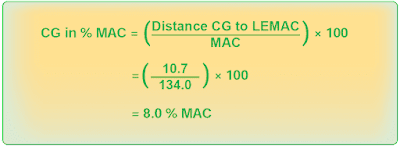
CG location: station 635.7
LEMAC: station 625
MAC: 134.0 in
- Determine the distance from the CG to the LEMAC by using the formula in Figure 2.
- Determine the location of the CG in percent MAC by using the formula found in Figure 3.


