Since large aircraft can carry substantial cargo, adding, subtracting, or moving any of the cargo from one hold to another can cause large shifts in the CG.
Effects of Loading or Offloading Cargo
Both the weight and CG of an aircraft are changed when cargo is loaded or offloaded.In the following example, the new weight and CG are calculated after 2,500 pounds of cargo is offloaded from the forward cargo hold
Aircraft specifications are
Loaded weight: 90,000 lb
Loaded CG: 22.5 percent MAC
Weight change: 2,500 lb
Forward cargo hold centroid: station 352.1
MAC: 141.5 in
LEMAC: station 549.13
1. Determine the CG location in inches from the datum before the cargo is removed. Do this by first determining the distance of the CG aft of the LEMAC. [Figure 1]
 |
| Figure 1. Determining the location of CG in inches before cargo is removed |
2. Determine the distance between the CG and the datum by adding the CG in inches aft of LEMAC to the distance from the datum to LEMAC. [Figure 2]
 |
| Figure 2. Determining the distance between CG and the datum |
3. Determine the moment/1,000 for the original weight. [Figure 3]
 |
| Figure 3. Determining the moment/1,000 for the original weight |
4. Determine the new weight and new CG by first determining the moment/1,000 of the removed weight. Multiply the weight removed (2,500 pounds) by the centroid of the forward cargo hold (352.1 inches), and then divide the result by 1,000. [Figure 4]
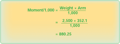 |
| Figure 4. Determining the moment/1,000 of the removed weight |
5. Subtract the removed weight from the original weight and subtract the moment/1,000 of the removed weight from the original moment/1,000. [Figure 5]
 |
| Figure 5. New weights and CG |
6. Determine the location of the new CG by dividing the total moment/1,000 by the total weight and multiplying this by the reduction factor of 1,000. [Figure 6]
 |
| Figure 6. Determining the location of new CG |
7. Convert the new CG location to percent MAC. First, determine the distance between the CG location and LEMAC. [Figure 7]
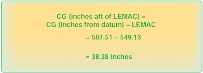 |
| Figure 7. Determining the distance between the CG and LEMAC |
8. Then, determine the new CG in percent MAC. [Figure 8]
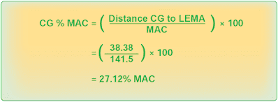 |
| Figure 8. Determining the new CG in percent MAC |
Loading 3,000 pounds of cargo into the forward cargo hold moves the CG forward 5.51 inches, from 27.12 percent MAC to 21.59 percent MAC.
Effects of Shifting Cargo From One Hold to Another
When cargo is shifted from one cargo hold to another, the CG changes, but the total weight of the aircraft remains the same.
For example, use the following data:
Loaded weight: 90,000 lb
Loaded CG: station 580.97 (22.5 percent MAC)
Forward cargo hold centroid: station 352
Aft cargo hold centroid: station 724.9
MAC: 141.5 in
LEMAC: station 549
To determine the change in CG (∆CG) caused by shifting 2,500 pounds of cargo from the forward cargo hold to the aft cargo hold, use the formula in Figure 9.
 |
| Figure 9. Calculating the change in CG, using index arms |
Since the weight was shifted aft, the CG moved aft and the CG change is positive. If the shift were forward, the CG change would be negative.
Before the cargo was shifted, the CG was located at station 580.97, which is 22.5 percent of MAC. The CG moved aft 10.36 inches, so the new CG is found using the formula from Figure 10.
 |
| Figure 10. Determining the new CG after shifting cargo weight |
Convert the location of the CG in inches aft of the datum to percent MAC by using the formula in Figure 11.
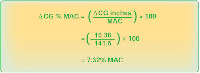 |
| Figure 11. Converting the location of CG to percent MAC |
The new CG in percent MAC caused by shifting the cargo is the sum of the old CG plus the change in CG. [Figure 12]
 |
| Figure 12. Determining the new CG in percent MAC |
Some AFMs locate the CG relative to an index point rather than the datum or the MAC. An index point is a location specified by the aircraft manufacturer from which arms used in weight and balance computations are measured. Arms measured from the index point are called index arms, and objects ahead of the index point have negative index arms, while those behind the index point have positive index arms.
Loaded CG: index arm of 0.97, which is 22.5 percent of MAC
Index point: fuselage station 580.0
Forward cargo hold centroid: –227.9 index arm
Aft cargo hold centroid: +144.9 index arm
MAC: 141.5 in
LEMAC: –30.87 index armThe weight was shifted 372.8 inches (–227.9 + Δ = +144.9, Δ =372.8).
The change in CG can be calculated by using this formula found in Figure 13.
 |
| Figure 13. Determining the change in CG caused by shifting 2,500 pounds of cargo |
Since the weight was shifted aft, the CG moved aft, and the CG change is positive. If the shift were forward, the CG change would be negative. Before the cargo was shifted, the CG was located at 0.97 index arm, which is 22.5 percent MAC. The CG moved aft 10.36 inches, and the new CG is shown using the formula in Figure 14.
 |
| Figure 14. Determining the new CG, moved aft 10.36 inches |
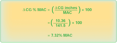
The change in the CG in percent MAC is determined by using the formula in Figure 15.
 |
| Figure 15. The change in the CG in percent MAC |
The new CG in percent MAC is the sum of the old CG plus the change in CG. [Figure 16]
 |
| Figure 16. The new CG in percent MAC |
Notice that the new CG is in the same location whether the distances are measured from the datum or from the index point.
Determining Cargo Pallet Loads and Floor Loading Limits
Each cargo hold has a structural floor loading limit based on the weight of the load and the area over which this weight is distributed. To determine the maximum weight of a loaded cargo pallet that can be carried in a cargo hold, divide its total weight, which includes the weight of the empty pallet and its tie down devices, by its area in square feet. This load per square foot must be equal to or less than the floor load limit.
In this example, determine the maximum load that can be placed on this pallet without exceeding the floor loading limit.
Pallet dimensions: 36 by 48 in
Empty pallet weight: 47 lb
Tie down devices: 33 lb
Floor load limit: 169 lb per square foot
The pallet has an area of 36 inches (3 feet) by 48 inches (4 feet), which equals 12 square feet, and the floor has a load limit of 169 pounds per square foot. Therefore, the total weight of the loaded pallet can be 169 × 12 = 2,028 pounds. Subtracting the weight of the pallet and the tie down devices gives an allowable load of 1,948 pounds (2,028 – [47 + 33]).
Determine the floor loading limit that is needed to carry a loaded cargo pallet having the following dimensions and weights:
Pallet dimensions: 48.5 by 33.5 in
Pallet weight: 44 lb
Tiedown devices: 27 lb
Cargo weight: 786.5 lb
First, determine the number of square feet of pallet area as shown in Figure 17.
 |
| Figure 17. Determining pallet area in square feet |
Then, determine the total weight of the loaded pallet:
Pallet: 44.0 lb
Tiedown devices: 27.0 lb
Cargo: 786.5 lb
Total: 857.5 lb
Determine the load imposed on the floor by the loaded pallet. [Figure 18] The floor must have a minimum loading limit of 76 pounds per square foot.
 |
| Figure 18. Determining the load imposed on the floor by the loaded pallet |
