Determining the Maximum Amount of Payload That Can Be Carried
The primary function of a transport or cargo aircraft is to carry payload, which is the portion of the useful load, passengers, or cargo that produces revenue. To determine the maximum amount of payload that can be carried, both the maximum limits for the aircraft and the trip limits imposed by the particular trip must be considered. In each of the following steps, the trip limit must be less than the maximum limit. If it is not, the maximum limit must be used.
These are the specifications for the aircraft in this example
Basic operating weight (BOW): 100,500 lb
Maximum zero fuel weight: 138,000 lb
Maximum landing weight: 142,000 lb
Maximum takeoff weight: 184,200 lb
Fuel tank load: 54,000 lb
Estimated fuel burn en route: 40,000 lb
1. Compute the maximum takeoff weight for this trip. This is the maximum landing weight plus the trip fuel. [Figure 1]
 |
| Figure 1. Finding the maximum takeoff weight |
2. The trip limit is lower than the maximum takeoff weight, so it is used to determine the zero fuel weight. [Figure 2]
 |
| Figure 2. Determining zero fuel weight with lower trip limits |
3. The trip limit is again lower than the maximum takeoff weight, so use it to compute the maximum payload for this trip. [Figure 3]
 |
| Figure 3. Finding maximum payload with lower trip limits |
Under these conditions, 27,500 pounds of payload may be carried.
Determining the Landing Weight
It is important to know the landing weight of the aircraft in order to set up the landing parameters and to be certain the aircraft is able to land safely at the intended destination.
In this example of a four-engine turboprop airplane, determine the airplane weight at the end of 4.0 hours of cruise under these conditions:
Takeoff weight: 140,000 lb
Pressure altitude during cruise: 16,000 ft
Ambient temperature during cruise: –32 °C
Fuel burned during descent and landing: 1,350 lb
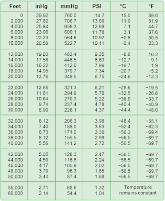
Refer to the U.S. Standard Atmosphere Table in Figure 4 and the gross weight table in Figure 5 when completing the following steps:
- Use the U.S. Standard Atmosphere Table to determine the standard temperature for 16,000 feet (–16.7 °C).
- The ambient temperature is –32 °C, which is a deviation from standard of 15.3 °C. (–32° – (–16.7°) = –15.3°). It is below standard.
- In the gross weight table, follow the vertical line representing 140,000 pounds gross weight upward until it intersects the diagonal line for 16,000 feet pressure altitude.
- From this intersection, draw a horizontal line to the left to the temperature deviation index (0 °C deviation).
- Draw a diagonal line parallel to the dashed lines for Below Standard from the intersection of the horizontal line and the Temperature Deviation Index.
- Draw a vertical line upward from the 15.3 °C Temperature Deviation From Standard.
- Draw a horizontal line to the left from the intersection of the Below Standard diagonal and the 15.3 °C temperature deviation vertical line. This line crosses the fuel flow–100 pounds per hour per engine index at 11.35 and indicates that each of the four engines burns 1,135 (100 × 11.35) pounds of fuel per hour. The total fuel burn for the 4-hour cruise is shown in Figure 6.
 |
| Figure 4. Standard atmosphere table |
 |
| Figure 5. Gross weight table |
 |
| Figure 6. Determining the total fuel burn for a 4-hour cruise |
The airplane gross weight was 140,000 pounds at takeoff with 18,160 pounds of fuel burned during cruise and 1,350 pounds burned during the approach and landing phase. This leaves a landing weight of 140,000 – (18,160 + 1,350) = 120,490 pounds.
Determining Fuel Dump Time in Minutes
Cruise weight: 171,000 lb
Maximum landing weight: 142,500 lb
Time from start of dump to landing: 19 minutes
Average fuel flow during
Dumping and descent: 3,170 lb/hr/eng
Fuel dump rate: 2,300 lb/minute
To calculate the fuel dump time in minutes:
1. Determine the amount of weight the aircraft must lose to reach the maximum allowable landing weight. [Figure 7]
 |
| Figure 7. Determining the amount of weight the aircraft must lose to reach the maximum allowable landing weight |
2. Determine the amount of fuel burned from the beginning of the dump to touchdown. [Figure 8]
 |
| Figure 8. Determining the amount of fuel burned from the beginning of the dump to touchdown |
For both engines, this is 52.83 × 2 = 105.66 lb/minute.
The engines burn 105.66 lbs of fuel per min for 19 minutes (the duration of the dump), which calculates to 2007.54 pounds of fuel burned between the beginning of the dump and touchdown.
 |
| Figure 9. Determining the amount of fuel needed to dump |
4. Determine the time needed to dump this amount of fuel by dividing the number of pounds of fuel to dump by the dump rate. [Figure 10]
 |
| Figure 10. Determine the time needed to dump fuel |
Weight and Balance of Commuter Category Airplanes
The Beech 1900 is a typical commuter category airplane that can be configured to carry passengers or cargo. Figure 11 shows the loading data of this type of airplane in the passenger configuration.
 |
| Figure 11. Loading data for passenger configuration |
Determining the Loaded Weight and CG
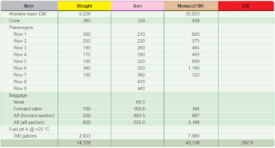
As this airplane is prepared for flight, a manifest is prepared.[Figure 12]
 |
| Figure 12. Determining the loaded weight and CG of a Beech 1900 in the passenger configuration |
1. The crew weight and the weight of each passenger is entered into the manifest. The moment/100 for each occupant is determined by multiplying the weight by the arm and dividing by 100. This data is available in the AFM and is shown in the Weight and Moments— Occupants table. [Figure 13]
 |
| Figure 13. Weight and moments—occupants |
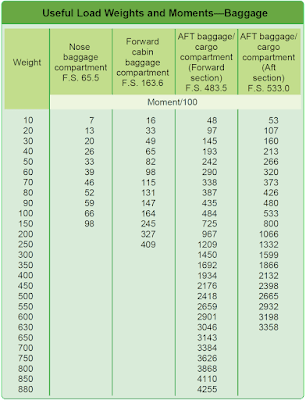
2. The weight of the baggage in each compartment used is entered with its moment/100. This is determined in the Weights and Moments—Baggage table. [Figure 14]
 |
| Figure 14. Weight and moments—baggage |
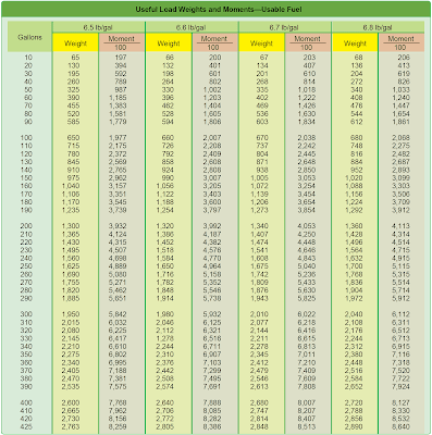
3. Determine the weight of the fuel. Jet A fuel has a nominal specific gravity at +15 °C of 0.812 and weighs 6.8 pounds per gallon, but at +25 °C, according to the Density Variation of Aviation Fuel Chart [Figure 15], it weighs 6.75 lb/gal. Using this chart, determine the weights and moment/100 for 390 gallons of Jet A fuel by interpolating between those for 6.7 lb/gal and 6.8 lb/gal. The 390 gallons of fuel at this temperature weighs 2,633 pounds, and its moment index is 7,866 lb-in/100.
 |
| Figure 15. Density variation of aviation fuel |
4. Add all of the weights and all of the moment indexes. Divide the total moment index by the total weight, and multiply this by the reduction factor of 100. The total weight is 14,729 pounds; the total moment index is 43,139 lb-in/100. The CG is located at fuselage station 292.9. [Figure 16]
 |
| Figure 16. Weights and moments—usable fuel |
5. Check to determine that the CG is within limits for this weight. Refer to the Weight and Balance Diagram. [Figure 17] Draw a horizontal line across the envelope at 14,729 pounds of weight and a vertical line from the CG of 292.9 inches aft of the datum. These lines cross inside the envelope, verifying the CG is within limits for this weight.
 |
| Figure 17. Weight and balance diagram |
Determining the Changes in CG When Passengers Are Shifted
Using the loaded weight and CG of the Beech 1900, calculate the change in CG when the passengers in rows 1 and 2 are moved to rows 8 and 9. [Figure 18] Note that there is no weight change, but the moment index has been increased by 1,155 pound-inches/100 to 44,294. The new CG is at fuselage station 300.7. [Figure 19]
 |
| Figure 18. Changes in CG caused by shifting passenger seats |
 |
| Figure 19. Determining the new CG at fuselage station |
This type of problem is usually solved by using the following two formulas. The total amount of weight shifted is 550 pounds (300 + 250) and both rows of passengers have moved aft by 210 inches (410 – 200 and 440 – 230). The CG has been shifted aft by 7.8 inches, and the new CG is at station 300.7. [Figure 20]
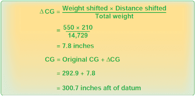 |
| Figure 20. Determining the new CG at station after CG has shifted aft |
In a large cabin aircraft with high-density seating such as the B737-800, the operator must account for the seating of passengers in the cabin [Figure 21]. If assigned seating is used to determine passenger location, the operator must implement procedures to ensure the assignment of passenger seating is incorporated into the loading procedure.
 |
| Figure 21. One passenger configuration of a B737-800 |
It is recommended that the operator take into account the possibility that some passengers may not sit in their assigned seats.
If the actual seating location of each passenger is not known, the operator may assume that all passengers are seated uniformly throughout the cabin or a specified subsection of the cabin. Reasonable assumptions can be made about the manner in which people distribute themselves throughout the cabin. For example, window seats are occupied first followed by aisle seats, followed by the remaining seats (window-aisle-remaining seating). Both forward and rear loading conditions should be considered. The passengers may fill up the window, aisle, and remaining seats from the front of the aircraft to the back, or the back to the front.
If necessary, the operator may divide the passenger cabin into subsections or zones and manage the loading of each zone individually. It can be assumed that passengers will be sitting uniformly throughout each zone.
Another consideration is the inflight movement of passengers, crew, and equipment. It is assumed that all passengers, crew, and equipment are secured when the aircraft is in the takeoff or landing configuration. Standard operating procedures should be taken into account. Examples of items that can move during flight are:
- Flight deck crew members moving to the lavatory.
- Flight attendants moving throughout the cabin.
- Service carts moving throughout the cabin.
- Passengers moving throughout the cabin.
- Passengers moving to the lavatory.
