Standard Rate Turns
The previous sections have addressed flying straight-and-level as well as climbs and descents. However, attitude instrument flying is not accomplished solely by flying in a straight line. At some point, the aircraft needs to be turned to maneuver along victor airways, global positioning system (GPS) courses, and instrument approaches. The key to instrument flying is smooth, controlled changes to pitch and bank. Instrument flying should be a slow but deliberate process that takes the pilot from departure airport to destination airport without any radical flight maneuvers.
A turn to specific heading should be made at standard rate. Standard rate is defined as a turning rate of 3 degrees per second, which yields a complete 360° turn in 2 minutes. A turning rate of 3 degrees per second allows for a timely heading change, as well as allowing the pilot sufficient time to cross-check the flight instruments and avoid drastic changes to the aerodynamic forces being exerted on the aircraft. At no time should the aircraft be maneuvered faster than the pilot is comfortable cross-checking the flight instruments. Most autopilots are programmed to turn at standard rate.
Establishing A Standard Rate Turn
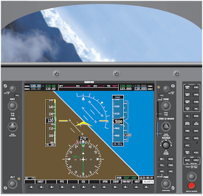
In order to initiate a standard rate turn, approximate the bank angle and then establish that bank angle on the attitude indicator. A rule of thumb to determine the approximate angle of bank is to use 15 percent of the true airspeed. A simple way to determine this amount is to divide the airspeed by 10 and add one-half the result. For example, at 100 knots, approximately 15° of bank is required (100/10 = 10 + 5 = 15); at 120 knots, approximately 18° of bank is needed for a standard-rate turn. Cross-check the turn rate indicator, located on the HSI, to determine if that bank angle is sufficient to deliver a standard rate turn. Slight modifications may need to be made to the bank angle in order to achieve the desired performance. The primary bank instrument in this case is the turn rate indicator since the goal is to achieve a standard rate turn. The turn rate indicator is the only instrument that can specifically indicate a standard rate turn. The attitude indicator is used only to establish a bank angle (control instrument) but can be utilized as a supporting instrument by cross-checking the bank angle to determine if the bank is greater or less than what was calculated.
 |
| Figure 1. Standard rate turn—constant airspeed |
When rolling out from a standard rate turn, the pilot needs to utilize coordinated aileron and rudder and roll-out to a wings level attitude utilizing smooth control inputs. The roll-out rate should be the same as the roll-in rate in order to estimate the lead necessary to arrive at the desired heading without over- or undershooting.
During the transition from the turn back to straight flight, the attitude indicator becomes the primary instrument for bank. Once the wings are level, the heading indicator becomes the primary instrument for bank. As bank decreases, the vertical component increases if the pitch attitude is not decreased sufficiently to maintain level flight. An aggressive cross-check keeps the altimeter stationary if forward control pressure is applied to the control column. As the bank angle is decreased, the pitch attitude should be decreased accordingly in order to arrive at the level pitch attitude when the aircraft reaches zero bank. Remember to utilize the trim wheel to eliminate any excess control forces that would otherwise need to be held.
Common Errors
- One common error associated with standard rate turns is due to pilot inability to hold the appropriate bank angle that equates to a standard rate. The primary bank instrument during the turn is the turn rate indicator; however, the bank angle varies slightly. With an aggressive cross-check, a pilot should be able to minimize errors arising from over- or underbanking.
- Another error normally encountered during standard rate turns is inefficient or lack of adequate crosschecking. Pilots need to establish an aggressive cross-check in order to detect and eliminate all deviations from altitude, airspeed, and bank angle during a maneuver.
- Fixation is a major error associated with attitude instrument flying in general. Pilots training for their instrument rating tend to focus on what they perceive to be the most important task at hand and abandon their cross-check by applying all of their attention to the turn rate indicator. A modified radial scan works well to provide the pilot with adequate scanning of all instrumentation during the maneuver.
Turns to Predetermined Headings
When determining what bank angle to utilize when making a heading change, a general rule states that for a small heading change, do not use a bank angle that is greater than the total number of degrees of change needed. For instance, if a heading change of 20° is needed, a bank angle of not more than 20° is required. Another rule of thumb that better defines the bank angle is half the total number of degrees of heading change required, but never greater than standard rate. The exact bank angle that equates to a standard rate turn varies due to true airspeed.
With this in mind and the angle of bank calculated, the next step is determining when to start the roll-out process. For example:
An aircraft begins a turn from a heading of 030° to a heading of 120°. With the given airspeed, a standard rate turn has yielded a 15° bank. The pilot wants to begin a smooth coordinated roll-out to the desired heading when the heading indicator displays approximately 112°. The necessary calculations are:
15° bank (standard rate) ÷ 2 = 7.5°
120° – 7.5° = 112.5°
By utilizing this technique, the pilot is better able to judge if any modifications need to be made to the amount of lead once the amount of over- or undershooting is established.
Timed Turns
Timed turns to headings are performed in the same fashion with an EFD as with an analog equipped aircraft. The instrumentation used to perform this maneuver is the turn rate indicator as well as the clock. The purpose of this maneuver is to allow the pilot to gain proficiency in scanning as well as to further develop the pilot’s ability to control the aircraft without standard instrumentation.
Timed turns become essential when controlling the aircraft with a loss of the heading indicator. This may become necessary due to a loss of the AHRS unit or the magnetometer. In any case, the magnetic compass is still available for navigation. The reason for timed turns instead of magnetic compass turns is the simplicity of the maneuver. Magnetic compass turns require the pilot to take into account various errors associated with the compass; timed turns do not.
Prior to initiating a turn, determine if the standard rate indication on the turn rate indicator actually delivers a 3 degrees per second turn. To accomplish this, a calibration must be made. Establish a turn in either direction at the indicated standard rate. Start the digital timer as the compass rolls past a cardinal heading. Stop the timer once the compass card rolls through another cardinal heading. Roll wings level and compute the rate of turn. If the turn rate indicator is calibrated and indicating correctly, 90° of heading change should take 30 seconds. If the time taken to change heading by 90° is more or less than 30 seconds, then a deflection above or below the standard rate line needs to be made to compensate for the difference. Once the calibration has been completed in one direction, proceed to the opposite direction. When both directions have been calibrated, apply the calibrated calculations to all timed turns.
In order to accomplish a timed turn, the amount of heading change needs to be established. For a change in heading from 120° to a heading of 360°, the pilot calculates the difference and divides that number by 3. In this case, 120° divided by 3° per second equals 40 seconds. This means that it would take 40 seconds for an aircraft to change heading 120° if that aircraft were held in a perfect standard rate turn. Timing for the maneuver should start as the aircraft begins rolling into the standard rate turn. Monitor all flight instruments during this maneuver. The primary pitch instrument is the altimeter. The primary power instrument is the ASI and the primary bank instrument is the turn rate indicator.
Once the calculated time expires, start a smooth coordinated roll-out. As long as the pilot utilizes the same rate of roll-in as roll-out, the time it takes for both will not need to be included in the calculations. With practice, the pilot should level the wings on the desired heading. If any deviation has occurred, make small corrections to establish the correct heading.
Compass Turns
The magnetic compass is the only instrument that requires no other source of power for operation. In the event of an AHRS or magnetometer failure, the magnetic compass is the instrument the pilot uses to determine aircraft heading. For a more detailed explanation on the use of the magnetic compass.
Steep Turns
For the purpose of instrument flight training, a steep turn is defined as any turn in excess of standard rate. A standard rate turn is defined as 3 degrees per second. The bank angle that equates to a turn rate of 3 degrees per second varies according to airspeed. As airspeed increases, the bank angle must be increased. The exact bank angle that equates to a standard rate turn is unimportant. Normal standard rate turn bank angles range from 10° to 20°. The goal of training in steep turn maneuvers is pilot proficiency in controlling the aircraft with excessive bank angles.
Training in excessive bank angles challenges the pilot in honing cross-checking skills and improves altitude control throughout a wider range of flight attitudes. Although the current instrument flight check practical test standards (PTS) do not call for a demonstration of steep turns on the certification check flight, this does not eliminate the need for the instrument pilot-in-training to demonstrate proficiency to an instructor.
Training in steep turns teaches the pilot to recognize and to adapt to rapidly changing aerodynamic forces that necessitate an increase in the rate of cross-checking all flight instruments. The procedures for entering, maintaining, and exiting a steep turn are the same as for shallower turns. Proficiency in instrument cross-check and interpretation is increased due to the higher aerodynamic forces and increased speed at which the forces are changing.
Performing the Maneuver
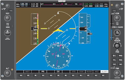
To enter a steep turn to the left, roll into a coordinated 45° bank turn to the left. An advantage that glass panel displays have over analog instrumentation is a 45° bank indication on the roll scale. This additional index on the roll scale allows the pilot to precisely roll into the desired bank angle instead of having to approximate it as is necessary with analog instrumentation. [Figure 2]
 |
| Figure 2. Steep left turn |
As soon as the bank angle increases from level flight, the vertical component of lift begins to decrease. If the vertical component of lift is allowed to continue to decrease, a pronounced loss of altitude is indicated on the altimeter along with the VSI tape, as well as the altitude trend indicator. Additionally, the airspeed begins to increase due to the lowered pitch attitude. It is very important to have a comprehensive scan developed prior to training in steep turns. Utilization of all of the trend indicators, as well the VSI, altimeter, and ASI, is essential in learning to fly steep turns by reference to instruments alone.
In order to avoid a loss of altitude, the pilot begins to slowly increase back pressure on the control yoke in order to increase the pitch attitude. The pitch change required is usually no more than 3 degrees to 5 degrees, depending on the type of aircraft. As the pilot increases back pressure, the angle of attack increases, thus increasing the vertical component of lift. When a deviation in altitude is indicated, proper control force corrections need to be made. During initial training of steep turns, pilots have a tendency to overbank. Over banking is when the bank angle exceeds 50°. As the outboard wing begins to travel faster through the air, it begins to generate a greater and greater differential in lift compared to the inboard wing. As the bank angle continues to progress more and more steeply past 45°, the two components of lift (vertical and horizontal) become inversely proportionate.
Once the angle has exceeded 45°, the horizontal component of lift is now the greater force. If altitude should continue to decrease and the pilot only applies back yoke pressure, the aircraft’s turn radius begins to tighten due to the increased horizontal force. If aft control pressure continues to increase, there comes a point where the loss of the vertical component of lift and aerodynamic wing loading prohibits the nose of the aircraft from being raised. Any increase in pitch only tightens the turning radius.
The key to successfully performing a steep turn by reference to instruments alone is the thorough understanding of the aerodynamics involved, as well as a quick and reliable crosscheck. The pilot should utilize the trim to avoid holding control forces for any period of time. With time and practice, a flight instructor can demonstrate how to successfully fly steep turns with and without the use of trim. Once the aircraft is trimmed for the maneuver, accomplishing the maneuver is virtually a hands-off effort. This allows additional time for cross-checking and interpreting the instruments.
It is imperative when correcting for a deviation in altitude, that the pilot modify the bank angle ±5° in order to vary the vertical component of lift, not just adjust back pressure. These two actions should be accomplished simultaneously. During the recovery from steep turns to straight-and-level flight, aft control forces must be varied with the power control to arrive back at entry altitude, heading and airspeed.
Steps:
- Perform clearing turns.
- Roll left into a 45° bank turn and immediately begin to increase the pitch attitude by approximately 3° to 5°.
- As the bank rolls past 30°, increase power to maintain the entry airspeed.
- Apply trim to eliminate any aft control wheel forces.
- Begin rolling out of the steep turn approximately 20° prior to the desired heading.
- Apply forward control pressure and place the pitch attitude in the level cruise pitch attitude.
- Reduce power to the entry power setting to maintain the desired airspeed.
- Re-trim the aircraft as soon as practical or continue into a right hand steep turn and continue from step 3.
- Once the maneuver is complete, establish cruise flight and accomplish all appropriate checklist items.
Unusual Attitude Recovery Protection
Unusual attitudes are some of the most hazardous situations for a pilot to be in. Without proper recovery training on instrument interpretation and aircraft control, a pilot can quickly aggravate an abnormal flight attitude into a potentially fatal accident.
Analog gauges require the pilot to scan between instruments to deduce the aircraft attitude. Individually, these gauges lack the necessary information needed for a successful recovery.
EFDs have additional features to aid in recognition and recovery from unusual flight attitudes. The PFD displays all the flight instruments on one screen. Each instrument is superimposed over a full-screen representation of the attitude indicator. With this configuration, the pilot no longer needs to transition from one instrument to another.
The new unusual attitude recovery protection allows the pilot to be able to quickly determine the aircraft’s attitude and make a safe, proper, and prompt recovery. Situational awareness is increased by the introduction of the large full-width artificial horizon depicted on the PFD. This now allows for the attitude indicator to be in view during all portions of the scan.
One problem with analog gauges is that the attitude indicator displays a complete blue or brown segment when the pitch attitude is increased toward 90° nose-up or nose-down.
With the EFDs, the attitude indicator is designed to retain a portion of both sky and land representation at all times. This improvement allows the pilot to always know the quickest way to return to the horizon. Situational awareness is greatly increased.
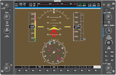
NOTE: The horizon line starts moving downward at approximately 47° pitch up. From this point on, the brown segment remains visible to show the pilot the quickest way to return to the level pitch attitude. [Figure 3]
 |
| Figure 3. Unusual attitude recovery protection. Note the brown horizon line is visible at the bottom |
NOTE: The horizon line starts moving upward at approximately 27° pitch down. From this point on, the blue segment remains visible to show the pilot the quickest way to return to the level pitch attitude. [Figure 4]
 |
| Figure 4. Horizon line starts moving upwards at 27°. Note that the blue sky remains visible at 17° nose down |
It is imperative to understand that the white line on the attitude indicator is the horizon line. The break between the blue and brown symbols is only a reference and should not be thought of as the artificial horizon.
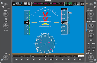
Another important advancement is the development of the unusual attitude recovery protection that is built into the PFD software and made capable by the AHRS. In the case of a nosehigh unusual attitude, the unusual attitude recovery protection displays red chevrons that point back to the horizon line. These chevrons are positioned at 50° up on the attitude indicator.
The chevrons appear when the aircraft approaches a nose-high attitude of 30°. The software automatically declutters the PFD leaving only airspeed, heading, attitude, altimeter, VSI tape, and the trend vectors. The decluttered information reappears when the pitch attitude falls below 25°.
In Figure 5, the aircraft has rolled past 60°. Observe the white line that continues from the end of the bank index. This line appears to indicate the shortest distance back to wings level.
 |
| Figure 5. Aircraft rolled past 60° |
When experiencing a failure of the AHRS unit, all unusual attitude protection is lost. The failure of the AHRS results in the loss of all heading and attitude indications on the PFD. In addition, all modes of the autopilot, except for roll and altitude hold, are lost.
The following picture series represents how important this technology is in increasing situational awareness, and how critical it is in improving safety.
Figure 6 shows the unusual attitude protection with valid AHRS and air data computer (ADC) inputs. The bright red chevrons pointing down to the horizon indicate a nose-high unusual attitude that can be easily recognized and corrected.
 |
| Figure 6. Unusual attitude protection with valid AHRS |
NOTE: The red chevrons point back to the level pitch attitude. The trend indicators show where the airspeed and altitude will be in 6 seconds. The trend indicator on the heading indicator shows which direction the aircraft is turning. The slip/skid indicator clearly shows if the aircraft is coordinated. This information helps the pilot determine which type of unusual attitude the aircraft has taken.
Now look at Figure 7. The display shows the same airspeed as the picture above; however, the AHRS unit has failed. The altimeter and the VSI tape are the only clear indications that the aircraft is in a nose-high attitude. The one key instrument that is no longer present is the slip/skid indicator. There is not a standby turn coordinator installed in the aircraft for the pilot to reference.
 |
| Figure 7. AHRS unit failed |
The magnetic compass indicates a heading is being maintained; however, it is not as useful as a turn coordinator or slip/skid indicator.
Figure 8 depicts an AHRS and ADC failure. In this failure scenario, there are no indications of the aircraft’s attitude. The manufacturer recommends turning on the autopilot, which is simply a wing leveler.
 |
| Figure 8. AHRS ADC failure |
With a failure of the primary instrumentation on the PFD, the only references available are the standby instruments. The standby instrumentation consists of an analog ASI, attitude indicator, altimeter, and magnetic compass. There is no standby turn coordinator installed.
In extreme nose-high or nose-low pitch attitudes, as well as high bank angles, the analog attitude indicator has the potential to tumble, rendering it unusable.
Autopilot Usage
The autopilot is equipped with inputs from a turn coordinator installed behind the MFD screen. This turn coordinator is installed solely for the use of the autopilot to facilitate the roll mode, which is simply a wing leveler. This protection is always available, barring a failure of the turn coordinator (to aid the pilot if the aircraft attains an unusual attitude).
NOTE: The pilot is not able to gain access to the turn coordinator. This instrument is installed behind the MFD panel. [Figure 9]
 |
| Figure 9. This autopilot requires roll information from a turn coordinator |
Most EFD equipped aircraft are coming from the factory with autopilots installed. However, the purchaser of the aircraft can specify if an autopilot is to be installed. Extreme caution should be utilized when flying an EFD equipped aircraft without an autopilot in IMC with an AHRS and ADC failure.
The autopilot should be utilized to reduce workload, which affords the pilot more time to monitor the flight. Utilization of the autopilot also decreases the chances of entry into an unusual attitude.
Flying an EFD-equipped aircraft without the use of an autopilot has been shown to increase workload and decrease situational awareness for pilots first learning to flying the new system.
Common Errors Leading to Unusual Attitudes
The following errors have the potential to disrupt a pilot’s situational awareness and lead to unusual attitudes.
- Improper trimming techniques. A failure to keep the aircraft trimmed for level flight at all times can turn a momentary distraction into an emergency situation if the pilot stops cross-checking.
- Poor crew resource management (CRM) skills. Failure to perform all single-pilot resource management duties efficiently. A major cause of CRM-related accidents comes from the failure of the pilot to maintain an organized flight deck. Items that are being utilized for the flight portion should be neatly arranged for easy access. A disorganized flight deck can lead to a distraction that causes the pilot to cease cross-checking the instruments long enough to enter an unusual attitude.
- Fixation is displayed when a pilot focuses far too much attention on one instrument because he or she perceives something is wrong or a deviation is occurring. It is important for the instrument pilot to remember that a cross-check of several instruments for corroboration is more valuable than checking a single instrument.
- Attempting to recover by sensory sensations other than sight. Recovery by instinct almost always leads to erroneous corrections due to the illusions that are prevalent during instrument flight.
- Failure to practice basic attitude instrument flying. When a pilot does not fly instrument approach procedures or even basic attitude instrument flying maneuvers for long periods of time, skill levels diminish. Pilots should avoid flying in IMC if they are not proficient. They should seek a qualified instructor to receive additional instruction prior to entry into IMC.
