
One of the major safety concerns in aviation is surface movement accidents. In response, the FAA has expanded the information available to pilots, including taxiway and runway information in FAA publications, particularly the IFR U.S. Terminal Procedures Publication (TPP) booklets and Chart Supplement (CS) volumes. The FAA has also implemented procedures and developed educational and awareness programs for pilots, air traffic control (ATC), and ground personnel. By focusing resources on this problem, the FAA aims to reduce and eventually eliminate surface movement accidents.
Table of Contents
Table of Contents
Airport Sketches and Diagrams
Airport sketches and diagrams provide pilots of all experience levels with graphical depictions of airport layouts. FAA Aeronautical Information Services (AIS), formerly known as Aeronautical Products (AeroNav), provides an airport sketch in the lower-left or lower-right portion of instrument approach charts. [Figure 1]
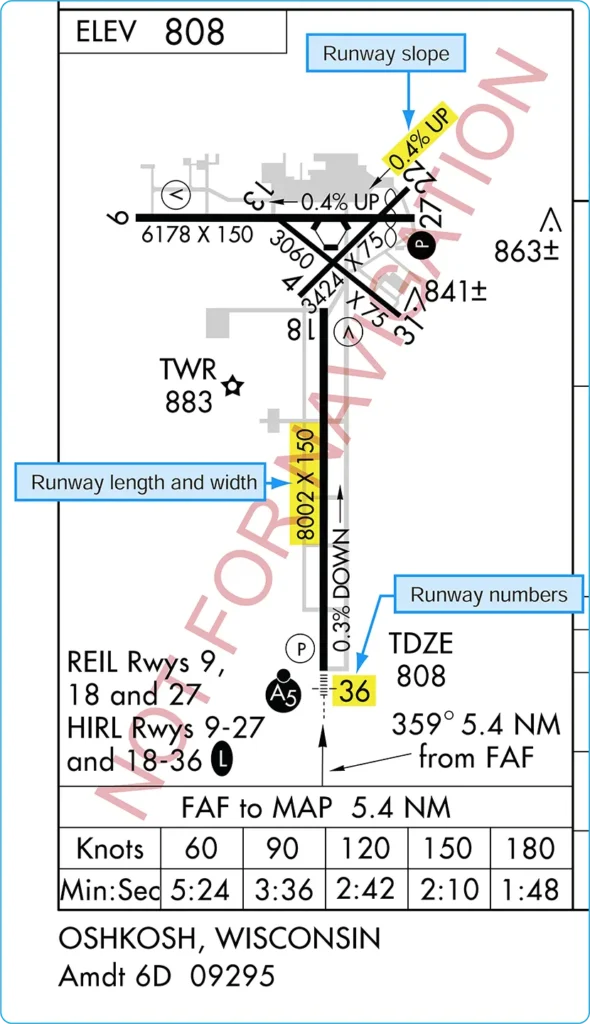
This sketch depicts runways, including their length, width, and slope; touchdown zone elevation; runway lighting systems; and taxiways. Graphical depictions of NOTAMs are also available for selected airports, as well as temporary flight restriction (TFR) areas, through the Defense Internet NOTAM Service (DINS).
For selected airports, typically those with heavy traffic or complex runway layouts, AIS also publishes an airport diagram. The diagram is located in the IFR TPP booklet following the instrument approach chart for that airport. It is a full-page depiction of the airport that includes the same features as the airport sketch, plus additional details such as taxiway identifiers, airport latitude and longitude, and building identification. Airport diagrams are also available in the Airport/Facility Directory section of the Chart Supplement (CS) and on the FAA’s Aeronautical Information Services website. [Figure 2]
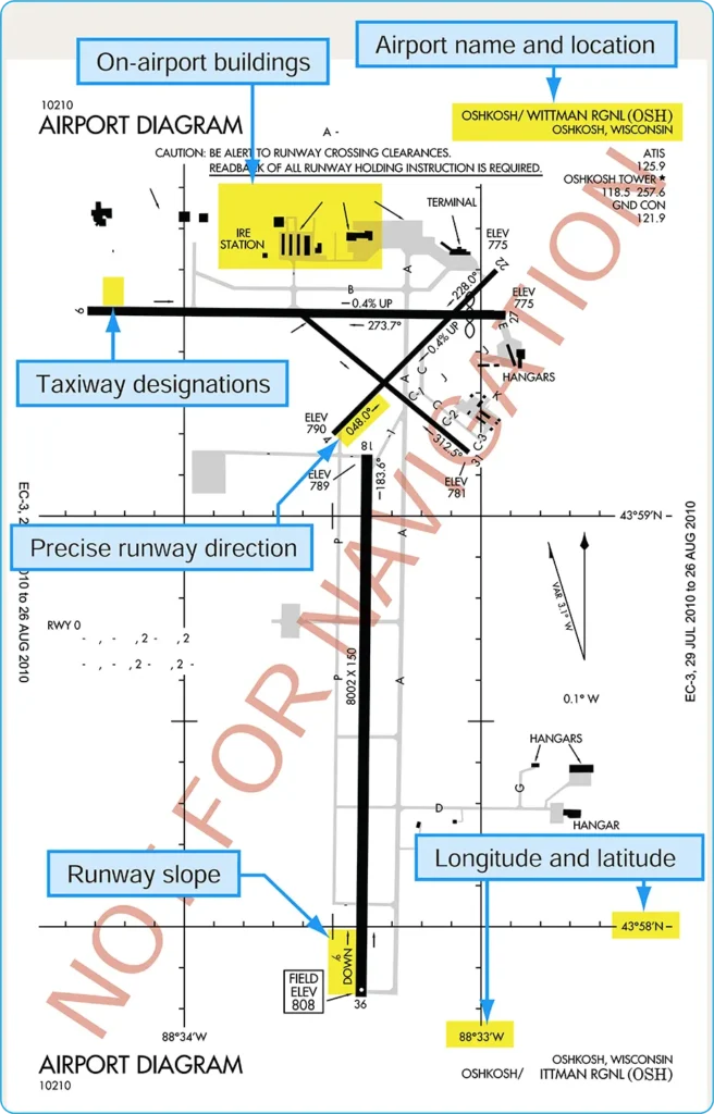
Chart Supplements (CS)
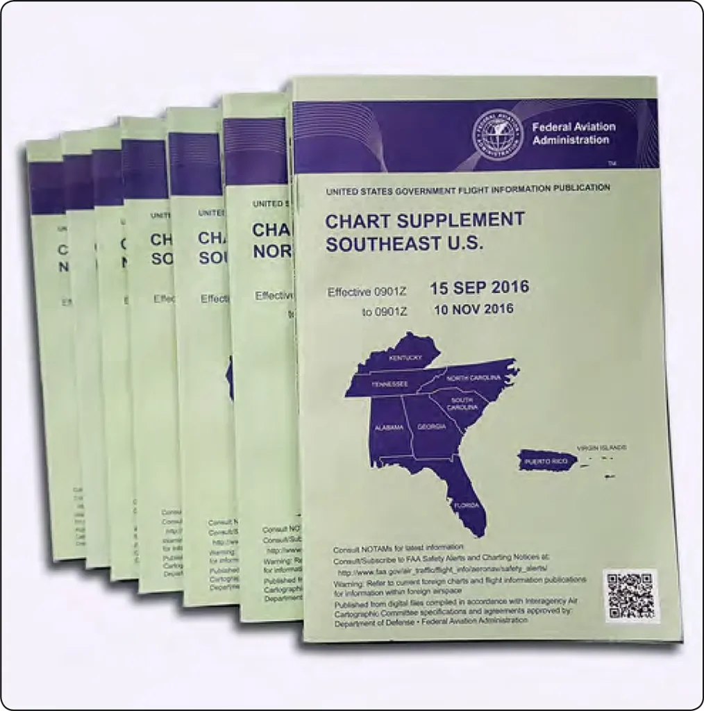
The former Airport/Facility Directory (A/FD) booklet was incorporated as a section of the Chart Supplement (CS). [Figure 3] The CS is published by Aeronautical Information Services in regional booklets and online through the Digital Chart Supplement (d-CS). The digital and printed products provide textual and graphic information about airports, including those used for visual flight rules (VFR) and instrument flight rules (IFR).
The A/FD section of the CS includes runway length and width, runway surface, load-bearing capacity, runway slope, runway declared distances, airport services, and hazards such as birds and reduced visibility. [Figure 4]
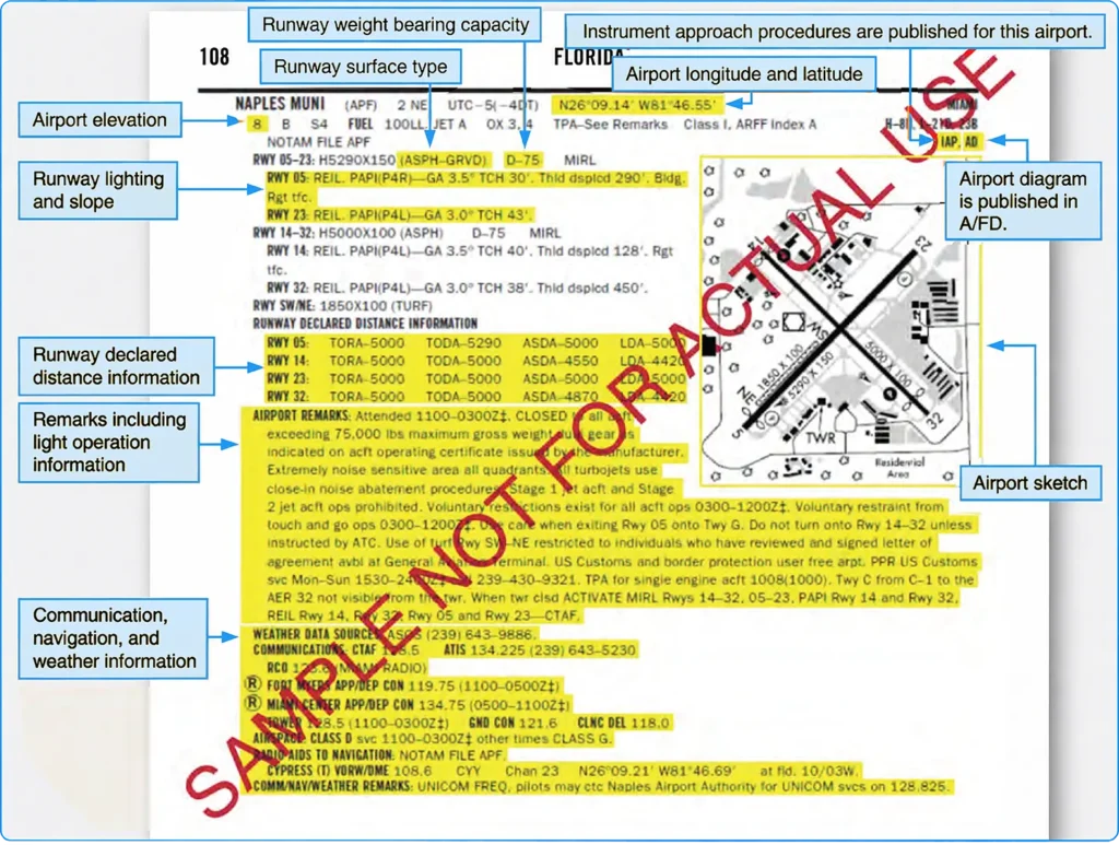
Airport sketches are also being added to aid VFR pilots in surface movement activities. In support of the FAA Runway Incursion Program, full-page airport diagrams and “Hot Spot” locations are included in the A/FD section of the CS. These diagrams are also published in the IFR TPP and are provided for airports with complex runway or taxiway layouts.
Surface Movement Guidance and Control System (SMGCS)
The Surface Movement Guidance and Control System (SMGCS) was developed to facilitate the safe movement of aircraft and vehicles at airports where scheduled air carriers conduct authorized operations in low-visibility conditions. FAA Advisory Circular (AC) 120-57 established guidance for SMGCS. The FAA has since updated this guidance; AC 120-57C, Low Visibility Operations/Surface Movement Guidance and Control Systems (LVO/SMGCS), was issued in 2023.
LVO/SMGCS plans provide procedures and enhanced visual aids for airport operations when runway visual range (RVR) is below 1,200 feet. The applicable plan establishes airport-specific roles, responsibilities, and procedures. Pilots, operators, and ground personnel should understand the low-visibility procedures applicable to the airport where they operate. Requirements and procedures can vary by airport and operator.
SMGCS low-visibility taxi plans enhance taxiway and runway signs, markings, and lighting, and may include SMGCS visual aid diagrams. [Figure 5]
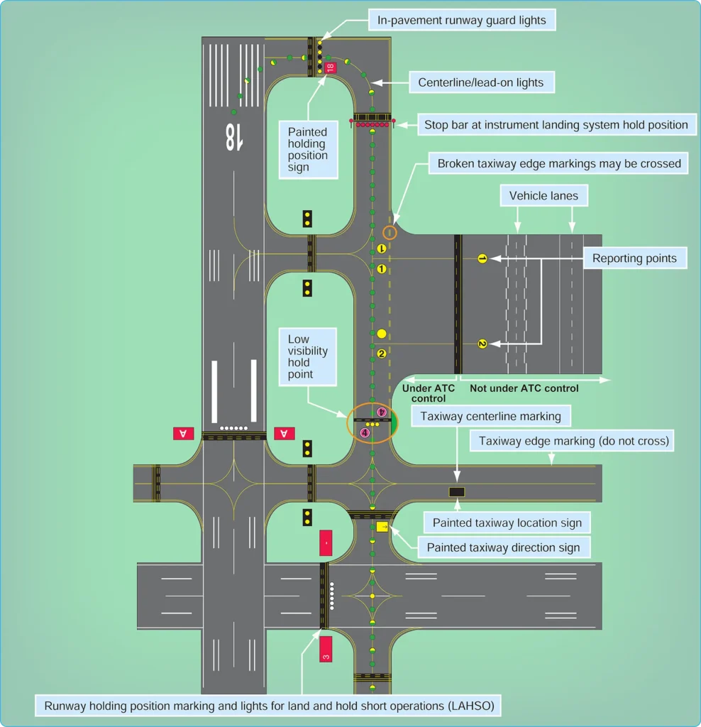
The plan also identifies taxi routes and their supporting facilities and equipment. Airport enhancements may include, but are not limited to:
- Controllable stop bar lights—These consist of a row of red, unidirectional, steady-burning in-pavement lights that can be controlled by ATC. They are installed at runway holding positions and help prevent unauthorized runway entry. When ATC authorizes an aircraft or vehicle to proceed, the stop bar is extinguished and the associated taxiway centerline lead-on lights are illuminated. Pilots must never cross an illuminated red stop bar, even if ATC has issued a clearance.
- Non-controllable stop bar lights—These are red, unidirectional lights installed at selected intersections where a restriction to movement is required. Their operation is governed by the airport’s applicable low-visibility procedures.
- Taxiway centerline lead-on lights—These guide ground traffic under low-visibility conditions and at night. The lights consist of alternating green and yellow in-pavement lights.
- Runway guard lights—These may be elevated or in-pavement and are installed at taxiway/runway intersections. They consist of alternately flashing yellow lights and enhance the conspicuity of the runway holding position.
- Geographic position markings—ATC may use geographic position markings to verify the position of aircraft and vehicles. The markings can be used as hold points or for position reporting. These checkpoints, sometimes called “pink spots,” are outlined with a black-and-white circle and designated with a number or a number and a letter.
- Clearance bar lights—These consist of three steady-burning yellow in-pavement lights used to denote holding positions for aircraft and vehicles. When used for hold points, they are colocated with geographic position markings.
Flight and ground crews, including Part 121 and Part 135 operators, must comply with applicable SMGCS plans when implemented at their airport. Airport tenants are responsible for disseminating information to employees and conducting training in low-visibility operating procedures. Anyone operating under an SMGCS plan must have access to the applicable low-visibility taxi route chart, which outlines taxi routes and other details concerning low-visibility operations. Part 91 operators should review and follow applicable airport procedures and the guidance in AC 120-57C. Follow Me assistance may be available at some airports, but its availability should not be assumed. An SMGCS outage that adversely affects operations is communicated through a Notice to Air Missions (NOTAM).
Advanced Surface Movement Guidance and Control System (A-SMGCS)
With increasing demand for airports to accommodate higher levels of aircraft movement, existing infrastructure can have difficulty safely handling greater traffic volumes in all weather conditions. As a result, the FAA has implemented runway safety systems, such as Airport Surface Detection Equipment, Model X (ASDE-X), and Advanced Surface Movement Guidance and Control System (A-SMGCS), at various airports. These systems use data from sources such as surface movement radar and aircraft transponders. Combining these data sources allows the systems to determine the position and identification of aircraft on the airport movement area and helps reduce the potential for collisions on runways and taxiways.
Additional information concerning airport lighting, markings, and signs can be found in the Aeronautical Information Manual (AIM) and the FAA Runway Safety website.
Airport Signs, Lighting, and Markings
Flight crews use airport lighting, markings, and signs to help maintain situational awareness. These visual aids provide information concerning the aircraft’s location on the airport, the taxiway in use, and the runway entrance being used. Overlooking this information can lead to preventable ground accidents. If you encounter unfamiliar markings or lighting, contact ATC for clarification and, if necessary, request progressive taxi instructions. Pilots are encouraged to notify the appropriate authorities of erroneous, misleading, or deteriorating signs or lighting that could compromise safe ground operations.
Runway Incursions
On any given day, the National Airspace System (NAS) may handle almost 200,000 takeoffs and landings. Due to the complex nature of the airport environment and the coordination required among the people who operate within it, the FAA continually works to maintain a high standard of airport safety. Runway safety is one of its top priorities. The FAA defines a runway incursion as: “Any occurrence at an aerodrome involving the incorrect presence of an aircraft, vehicle, or person on the protected area of a surface designated for the landing and takeoff of aircraft.”
The four categories of runway incursions are listed below:
- Category A—a serious incident in which a collision was narrowly avoided.
- Category B—an incident in which separation decreases and there is significant potential for a collision, possibly requiring a time-critical corrective or evasive response to avoid one.
- Category C—an incident characterized by ample time and/or distance to avoid a collision.
- Category D—an incident that meets the definition of a runway incursion, such as the incorrect presence of a single vehicle, person, or aircraft on the protected area of a surface designated for landing and takeoff, but with no immediate safety consequences.
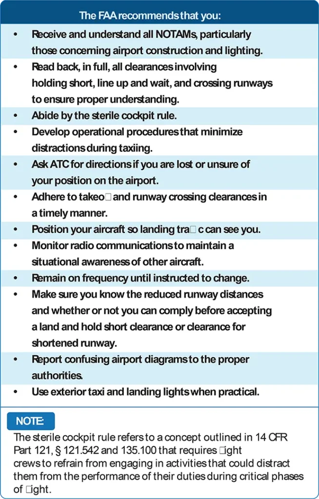
Figure 6 highlights several steps that reduce the chances of being involved in a runway incursion.
In addition to the SMGCS program, the FAA has implemented other programs to reduce runway incursions and surface movement issues. These include identifying runway hotspots, designing standardized taxi routes, and implementing the Runway Safety Program.
Runway Hotspots
The International Civil Aviation Organization (ICAO) defines a runway hotspot as a location on an aerodrome movement area with a history or potential risk of collision or runway incursion, where heightened attention by pilots and drivers is necessary. Hotspots alert pilots to complex or potentially confusing taxiway geometry that could make surface navigation challenging. Pilots should be aware that these hazardous intersections exist and remain especially vigilant when approaching and taxiing through them. Hotspots are depicted on some airport charts as circled areas. [Figure 7]
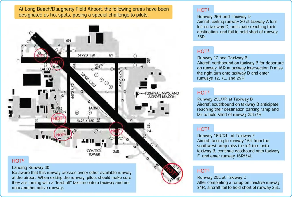
The FAA Office of Runway Safety provides links to FAA regions that maintain lists of airports with runway hotspots through the FAA Runway Safety website.
Standardized Taxi Routes
Standardized taxi routes improve ground management at high-density airports, particularly those with airline service. At these airports, typical taxiway traffic patterns used to move aircraft between gates and runways are established and coded. An ATC specialist can reduce radio communication time and the potential for taxi-instruction misinterpretation by clearing a pilot to taxi via a specific, named route. An example is Los Angeles International Airport (KLAX), where the North Route is used to transition to Runway 24L. [Figure 8]
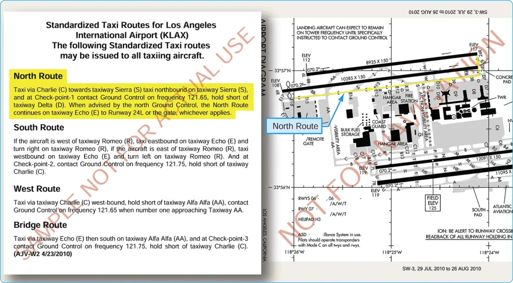
These routes are issued by ground control. If unable to comply, pilots must advise ground control on initial contact. If a pilot becomes uncertain about the assigned taxi route, a request should be made for progressive taxi instructions. Step-by-step routing directions may also be issued when the controller deems them necessary because of traffic, closed taxiways, airport construction, or other conditions. It is the pilot’s responsibility to determine whether an airport has preplanned taxi routes, become familiar with them, and have the applicable taxi descriptions available. Information about airports that use coded taxiway routes may be provided in the Notices to Airmen Publication (NTAP) and other applicable airport publications.
Taxi and Movement Operations
On June 30, 2010, controllers began applying procedures requiring explicit instructions to cross or hold short of each runway that intersects a taxi route. The following summarizes the key safety principles:
- “Taxi to” is no longer used when issuing taxi instructions to an assigned takeoff runway.
- Instructions to cross a runway are issued one runway at a time. Instructions to cross multiple runways are not issued. An aircraft or vehicle must have crossed the previous runway before another runway-crossing instruction is issued. This applies to any runway, including inactive or closed runways.
- Never cross a runway holding position marking without explicit ATC instructions. If in doubt, ask ATC for clarification.
Reminder: You may not enter a runway unless you have been:
- Instructed to cross or taxi onto that specific runway;
- Cleared to take off from that runway; or
- Instructed to line up and wait on that specific runway.
For more information, refer to FAA Order JO 7110.65, Air Traffic Control, available through the FAA website.