Instrument departure procedures are preplanned IFR procedures that provide obstruction clearance from the terminal area to the appropriate en route structure. Primarily, these procedures are designed to provide obstacle protection for departing aircraft. There are two types of Departure Procedures (DPs):
- Obstacle Departure Procedures (ODPs) and
- Standard Instrument Departures (SIDs).
When an instrument approach is initially developed for an airport, the need for an ODP is assessed. If an aircraft may turn in any direction from a runway within the limits of the assessment area and remain clear of obstacles that runway passes what is called a diverse departure assessment, and no ODP is published. A diverse departure assessment ensures that a prescribed, expanding amount of required obstacle clearance (ROC) is achieved during the climb-out until the aircraft can obtain a minimum 1,000 feet ROC in non-mountainous areas or a minimum 2,000 feet ROC in mountainous areas. Unless specified otherwise, required obstacle clearance for all departures, including diverse, is based on the pilot crossing the departure end of the runway (DER) at least 35 feet above the DER elevation, climbing to 400 feet above the DER elevation before making the initial turn, and maintaining a minimum climb gradient of 200 ft/ NM, unless required to level off by a crossing restriction, until the minimum IFR altitude is reached. Following ODP assessment, a SID may still be established for the purposes of ATC flow management, system enhancement, or noise abatement.
Design Criteria
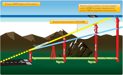
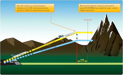
The design of a departure procedure is based on FAA Order 8260.3, United States Standard for Terminal Instrument Procedures (TERPS), which is a living document that is updated frequently. Departure design criterion begins with the assumption of an initial climb of 200 ft/NM after crossing the DER at a height of at least 35 feet. [Figure 1] The aircraft climb path assumption provides a minimum of 35 feet of additional obstacle clearance above the required obstacle clearance (ROC), from the DER outward, to absorb variations ranging from the distance of the static source to the landing gear, to differences in establishing the minimum 200 ft/NM climb gradient, etc. The ROC is the planned separation between the obstacle clearance surface (OCS) and the required climb gradient of 200 ft/NM. The ROC value is zero at the DER elevation and increases along the departure route until the ROC value appropriate for en route flight is achieved. The appropriate ROC value for en route operations is typically achieved about 25 NM for 1,000 feet of ROC in non-mountainous areas, and 46 NM for 2,000 feet of ROC in mountainous areas.
If taking off from a runway using a diverse departure (a runway without a published ODP), beyond these distances the pilot is responsible for obstacle clearance if not operating on a published route, and if below the MEA or MOCA of a published route, or below an ATC-assigned altitude. [Figure 2]
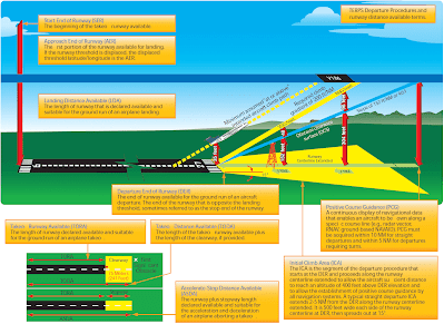
Recent changes in TERPS criteria make the OCS lower and more restrictive. [Figure 3] However, there are many departures today that were evaluated under the old criteria that allowed some obstacle surfaces to be as high as 35 feet at the DER. [Figure 1] Since there is no way for the pilot to determine whether the departure was evaluated using the previous or current criteria, and until all departures have been evaluated using the current criteria, pilots need to be very familiar with the departure environment and associated obstacles, especially if crossing the DER at less than 35 feet.
All departure procedures are initially assessed for obstacle clearance based on a 40:1 Obstacle Clearance Surface (OCS). If no obstacles penetrate this 40:1 OCS, the standard 200 ft/NM climb gradient provides a minimum of 48 ft/NM of clearance above objects that do not penetrate the slope. The departure design must also include the acquisition of positive course guidance (PCG), typically within 5 to 10 NM of the DER for straight departures. Even when aircraft performance greatly exceeds the minimum climb gradient, the published departure routing must always be flown.
Airports publish the declared distances in the A/FD section of the CS. These include takeoff runway available (TORA), takeoff distance available (TODA), accelerate-stop distance available (ASDA), and landing distance available (LDA). These distances are calculated by adding to the full length of paved runway any applicable clearway or stop-way and subtracting from that sum the sections of the runway unsuitable for satisfying the required takeoff run, takeoff, accelerate/stop, or landing distance as shown in Figure 3.
Optimally, the 40 to 1 slope would work for every departure design; however, due to terrain and manmade obstacles, it is often necessary to use alternative requirements to accomplish a safe, obstacle-free departure design. In such cases, the design of the departure may incorporate a climb gradient greater than 200 ft/NM, an increase in the standard takeoff minimums to allow the aircraft to “see and avoid” the obstacles, a standard climb of 200 ft/NM with a specified reduced takeoff length, or a combination of these options and a specific departure route.
If a departure route is specified, it must be flown in conjunction with the other options.
The obstacle environment may require a climb gradient greater than 200 ft/NM. In these cases, the ROC provided above obstacles is equivalent to 24 percent of the published climb gradient. The required climb gradient, for obstacle purposes on ODPs and SIDs, is obtained by using the formulas:
Standard Formula
DoD Option*
O = obstacle mean sea level (MSL) elevation
E = climb gradient starting MSL elevation
D = distance (NM) from DER to the obstacle
Examples:
These formulas are published in FAA Order 8260.3 for calculating the required climb gradient to clear obstacles.
The following formula is used for calculating SID climb gradients for other than obstacles (i.e., ATC requirements):
A = “climb to” altitude
E = climb gradient starting MSL elevation
D = distance (NM) from the beginning of the climb
Example:
Note: The climb gradient must be equal to or greater than the gradient required for obstacles along the route of flight.
The published climb gradient, obstacle or otherwise, is treated as a plane which must not be penetrated from above until reaching the stated height or has reached the en route environment (e.g., above the MEA, MOCA). Departure design, including climb gradients, does not take into consideration the performance of the aircraft; it only considers obstacle protection for all aircraft. TERPS criteria assume the aircraft is operating with all available engines and systems fully functioning. Development of contingency procedures, required to cover the case of an engine failure, engine out procedures (EOPs) or other emergency in flight that may occur after liftoff, is the responsibility of the operator. When a climb gradient is required for a specific departure, it is vital that pilots fully understand the performance of their aircraft and determine if it can comply with the required climb. The standard climb of 200 ft/NM is not an issue for most aircraft. When an increased climb gradient is specified due to obstacle issues, it is important to calculate aircraft performance, particularly when flying out of airports at higher altitudes on warm days. To aid in the calculations, the front matter of every TPP booklet contains a rate of climb table that relates specific climb gradients and typical groundspeeds. [Figure 4].
Low, Close-In Obstacles
Obstacles that are located within 1 NM of the DER and penetrate the 40:1 OCS are referred to as “low, close-in obstacles” and are also included in the TPP. These obstacles are less than 200 feet above the DER elevation, within 1 NM of the runway end, and do not require increased takeoff minimums. The standard ROC to clear these obstacles would require a climb gradient greater than 200 ft/NM for a very short distance, only until the aircraft was 200 feet above the DER. To eliminate publishing an excessive climb gradient, the obstacle above ground level (AGL)/ MSL height and location relative to the DER is noted in the Takeoff Minimums and (Obstacle) Departure Procedures section of a given TPP booklet. The purpose of this note is to identify the obstacle and alert the pilot to the height and location of the obstacle so they can be avoided. This can be accomplished in a variety of ways:
- The pilot may be able to see the obstruction and maneuver around the obstacle(s) if necessary;
- Early liftoff/climb performance may allow the aircraft to cross well above the obstacle(s);
- If the obstacle(s) cannot be visually acquired during departure, preflight planning should take into account what turns or other maneuver(s) may be necessary immediately after takeoff to avoid the obstruction(s).
These obstacles are especially critical to aircraft that do not lift off until close to the DER or which climb at the minimum rate. [Figure 5]
One-Engine-Inoperative (OEI) Takeoff Obstacle Clearance Requirements
Large and turbine-powered, multiengine transport category airplanes and commuter category airplanes operated under Part 121 or Part 135 have additional takeoff obstacle clearance requirements beyond the scope of the IFR departure procedure requirements addressed by TERPS.
Part 25 transport category and Part 23 commuter category airplane certification rules define the one-engineinoperative (OEI) takeoff flight path, which is normally constructed from a series of segments beginning from 35 feet above the runway surface at the end of the OEI takeoff distance and ending at a minimum height of 1,500 feet above the runway elevation. However, the OEI net takeoff flight path assessment may continue above 1,500 feet if necessary to ensure obstacle clearance.
The actual, or gross, OEI flight path represents the vertical OEI climb profile that the aircraft has been demonstrated capable of achieving using takeoff procedures developed for line operations based on the aircraft’s weight, configuration, and environmental conditions at the time of takeoff. The OEI net takeoff flight path represents the actual OEI takeoff flight path that has been degraded by an amount specified by the certification rules to provide a safety margin for expected variations under operational conditions. Subpart I of Part 121 and Part 135 require that the OEI net takeoff flight path be at least 35 feet above obstacles that are located within the prescribed lateral distance either side of the flight path The actual obstacle clearance capability, under optimum conditions after experiencing an engine failure on takeoff, is equal to the difference between gross and net flight path, plus the additional 35 feet. [Figure 6]
 |
| Figure 6. Part 25 turbine-powered, transport category airplane OEI actual (gross) takeoff flight path and OEI net takeoff flight path |
Advisory Circular (AC) 120-91, Airport Obstacle Analysis, provides guidance and acceptable criteria for use in determining the safe lateral clearance from obstacles, when developing takeoff and initial climb out airport obstacle analyses and engine out obstacle avoidance procedures to comply with the intent of these regulatory requirements. Pilots departing an airport under IFR and operating under Part 121 or 135 are required by 14 CFR 91.175(f )(4) to use an engine-inoperative takeoff obstacle clearance or avoidance procedure that assures compliance with the obstacle clearance requirements (subpart I) of those rules. The assessment of OEI takeoff obstacle clearance is separate and independent of the IFR departure procedure and associated all-engines-operating climb gradient requirements. While the Part 91 operating rules governing large, commuter, and turbine-powered aircraft do not require the use of an OEI takeoff obstacle clearance or avoidance procedure, such use is encouraged for Part 91 operators of these aircraft.
Unlike TERPS, which assesses obstacle clearance beginning at the DER, the OEI net takeoff flight path obstacle assessment begins at the point where the aircraft reaches 35 feet above the runway at the end of the OEI takeoff distance. Therefore, the OEI net takeoff flight path assessment may begin before the DER allowing for the use of a portion of the runway for the OEI climb. The OEI net takeoff flight path obstacle clearance assessment must also account for clearance of the low, close-in obstacles that are noted on the IFR departure procedure, but are not necessarily cleared when complying with the TERPS-based IFR climb gradient.
The OEI net takeoff flight path is unique for each aircraft type and is assessed on each takeoff for the required obstacle clearance directly against those obstacles located beneath the OEI flight track and within the prescribed lateral distance from the flight path centerline. TERPS, on the other hand, provides a required climb gradient that represents a surface that the aircraft’s all-engines-operating climb profile must remain above throughout the IFR climb until reaching the en route environment. These two methods of assessing obstacle clearance are necessarily quite different. TERPS is used by the procedure designer to determine a lateral path that is usable by a wide variety of aircraft types, and establishes a clearance plane that aircraft must be able to stay above to fly the procedure. A Part 25 transport category and Part 23 commuter category aircraft’s OEI takeoff flight path is established by or on behalf of the operator for a particular aircraft type and then limit weights are determined that assure clearance of any obstacles under that flight path (or within the prescribed lateral distance from the flight path centerline).
It may be necessary for pilots and operators of these categories of aircraft to use the services of an aircraft performance engineer or airport/runway analysis service provider as means of compliance with the requirements of Part 121 subpart I, or Part 135 subpart I concerning OEI net takeoff flight obstacle clearance and takeoff field length requirements. [Figure 7] Airport/runway analysis involves the complex, usually computerized, computations of aircraft performance, using extensive airport/obstacle databases and terrain information. This yields maximum allowable takeoff and landing weights for particular aircraft/engine configurations for a specific airport, runway, and range of temperatures. The computations also consider flap settings, various aircraft characteristics, runway conditions, obstacle clearance, and weather conditions. Obstacle data also is available from these service providers for operators who desire to perform their own analysis using the OEI climb performance and flight path data furnished in the Airplane Flight Manual or when using an aircraft electronic performance program supplied by the manufacturer or other service provider.
Airport/runway analysis is typically based on the assumption that the pilot will fly a straight-out departure following an engine failure on takeoff. However, when a straight-out departure is not practical or recommended, a special OEI turn procedure can be developed for each applicable runway. This OEI turn procedure may follow the path of a published IFR departure procedure or it may follow an independent path designed to avoid otherwise onerous obstacles and thereby maximize the allowable takeoff weight and payload. Graphic depiction of the OEI procedure is often available to give the pilot a pictorial representation of the special OEI procedure. An engine failure during takeoff is a non-normal condition; therefore, the actions taken by the pilot including the use of an OEI turn procedure takes precedence over noise abatement, air traffic, SIDs, DPs, and other normal operating considerations.
It must be understood that the airport/runway analysis assesses obstacle clearance using the OEI net takeoff flight path data provided in the Airplane Flight Manual and the selected lateral obstacle assessment area. A takeoff weight limit provided on the analysis does not necessarily ensure compliance with the all-engines-operating climb gradient published on an IFR departure procedure even if the track of the OEI special procedure and the IFR departure procedure are identical.


