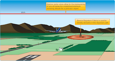
There are two types of DPs: those developed to assist pilots in obstruction avoidance, known as ODPs, printed either textually or graphically, and those developed to communicate ATC clearances, SIDs, always printed graphically.
Obstacle Departure Procedures (ODPs)
The term ODP is used to define procedures that simply provide obstacle clearance. ODPs are only used for obstruction clearance and do not include ATC-related climb requirements. In fact, the primary emphasis of ODP design is to use the least restrictive route of flight to the en route structure or to facilitate a climb to an altitude that allows random (diverse) IFR flight, while attempting to accommodate typical departure routes.
An ODP must be developed when obstructions penetrate the 40:1 departure OCS, as described in FAA Order 8260.3. Only one ODP will be established for a particular runway. This is considered the default IFR departure procedure for a given runway and is intended for pilot awareness and use in the absence of ATC radar vectors or SID assignment. Text is not published to allow an option to use a SID or alternate maneuver assigned by ATC (e.g., “Climb heading 330 to 1200 before turning or use Manchester Departure” or “Turn right, climb direct ABC very high frequency (VHF) omnidirectional range (VOR) or as assigned by ATC.”). ODPs are textual in nature. However, due to the complex nature of some procedures, a visual presentation may be necessary for clarification and understanding. If the ODP is charted graphically, the chart itself includes the word “Obstacle” in parentheses in the title. Additionally, all newly-developed RNAV ODPs are issued in graphical form.
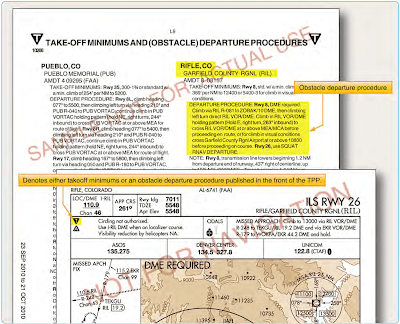
All ODPs are listed in the front of the Aeronautical Information Services approach chart booklets under the heading Takeoff Minimums and Obstacle Departure Procedures. Each procedure is listed in alphabetical order by city and state. The ODP listing in the front of the booklet includes a reference to the graphic chart located in the main body of the booklet if one exists. [Figure 1]
ODP Flight Planning Considerations
ODPs are not assigned by ATC unless absolutely necessary to achieve aircraft separation. It is the pilot’s responsibility to determine if there is an ODP published for that airport. If a Part 91 pilot is not given a clearance containing an ODP, SID, or radar vectors and an ODP exists, compliance with such a procedure is the pilot’s choice. A graphic ODP may also be filed in an instrument flight plan by using the computer code included in the procedure title. As a technique, the pilot may enter “will depart (airport) (runway) via textual ODP” in the remarks section of the flight plan. Providing this information to the controller clarifies the intentions of the pilot and helps prevent a potential pilot/controller misunderstanding. If the ODP is not included in the pilot’s clearance, the pilot should inform ATC when an ODP is used for departure from a runway so that ATC can ensure appropriate traffic separation.
During planning, pilots need to determine whether or not the departure airport has an ODP. Remember, an ODP can only be established at an airport that has instrument approach procedures (IAPs). An ODP may drastically affect the initial part of the flight plan. Pilots may have to depart at a higher than normal climb rate, or depart in a direction opposite the intended heading and maintain that for a period of time, any of which would require an alteration in the flight plan and initial headings. Considering the forecast weather, departure runways, and existing ODP, plan the flight route, climb performance, and fuel burn accordingly to compensate for the departure procedure.
Additionally, when close-in obstacles are noted in the Takeoff Minimums and (Obstacle) Departure Procedures section, it may require the pilot to take action to avoid these obstacles. Consideration must be given to decreased climb performance from an inoperative engine or to the amount of runway used for takeoff. Aircraft requiring a short takeoff roll on a long runway may have little concern. On the other hand, airplanes that use most of the available runway for takeoff may not have the standard ROC when climbing at the normal 200 ft/NM.
Another factor to consider is the possibility of an engine failure during takeoff and departure. During the preflight planning, use the aircraft performance charts to determine if the aircraft can still maintain the required climb performance. For high performance aircraft, an engine failure may not impact the ability to maintain the prescribed climb gradients. Aircraft that are performance limited may have diminished capability and may be unable to maintain altitude, let alone complete a climb to altitude. Based on the performance expectations for the aircraft, construct an emergency plan of action that includes emergency checklists and the actions to take to ensure safety in this situation.
Standard Instrument Departures (SIDs)
A SID is an ATC-requested and developed departure route, typically used in busy terminal areas. It is designed at the request of ATC in order to increase capacity of terminal airspace, effectively control the flow of traffic with minimal communication, and reduce environmental impact through noise abatement procedures.
While obstacle protection is always considered in SID routing, the primary goal is to reduce ATC/pilot workload while providing seamless transitions to the en route structure. ATC clearance must be received prior to flying a SID. SIDs also provide additional benefits to both the airspace capacity and the airspace users by reducing radio congestion, allowing more efficient airspace use, and simplifying departure clearances. All of the benefits combine to provide effective, efficient terminal operations, thereby increasing the overall capacity of the NAS.
If you cannot comply with a SID, if you do not possess the charted SID procedure, or if you simply do not wish to use SIDs, include the statement “NO SIDs” in the remarks section of your flight plan. Doing so notifies ATC that they cannot issue you a clearance containing a SID, but instead will clear you via your filed route to the extent possible, or via a Preferential Departure Route (PDR). It should be noted that SID usage not only decreases clearance delivery time, but also greatly simplifies your departure, easing you into the IFR structure at a desirable location and decreases your flight management load. While you are not required to depart using a SID, it may be more difficult to receive an “as filed” clearance when departing busy airports that frequently use SID routing.
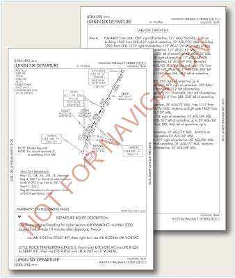
SIDs are always charted graphically and are located in the TPP after the last approach chart for an airport. The SID may be one or two pages in length, depending on the size of the graphic and the amount of space required for the departure description. Each chart depicts the departure route, navigational fixes, transition routes, and required altitudes. The departure description outlines the particular procedure for each runway. [Figure 2]
Transition Routes
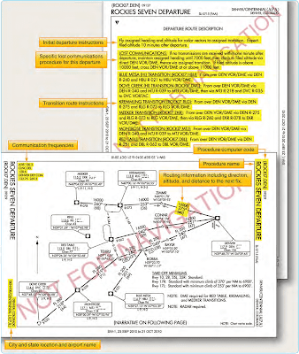
Charted transition routes allow pilots to transition from the end of the basic SID to a location in the en route structure. Typically, transition routes fan out in various directions from the end of the basic SID to allow pilots to choose the transition route that takes them in the direction of intended departure. A transition route includes a course, a minimum altitude, and distances between fixes on the route. When filing a SID for a specific transition route, include the transition in the flight plan, using the correct departure and transition code. ATC also assigns transition routes as a means of putting the flight on course to the destination. In any case, the pilot must receive an ATC clearance for the departure and the associated transition, and the clearance from ATC will include both the departure name and transition (e.g., Joe Pool Nine Departure, College Station Transition). [Figure 3]
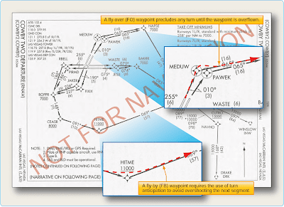
The SID is designed to allow the pilot to provide his or her own navigation with minimal radio communication. This type of procedure usually contains an initial set of departure instructions followed by one or more transition routes. A SID may include an initial segment requiring radar vectors to help the flight join the procedure, but the majority of the navigation remains the pilot’s responsibility. [Figure 4]
A radar SID usually requires ATC to provide radar vectors from just after takeoff (ROC is based on a climb to 400 feet above the DER elevation before making the initial turn) until reaching the assigned route or a fix depicted on the SID chart. Radar SIDs do not include departure routes or transition routes because independent pilot navigation is not involved. The procedure sets forth an initial set of departure instructions that typically include an initial heading and altitude. ATC must have radar contact with the aircraft to be able to provide vectors. ATC expects you to immediately comply with radar vectors, and they expect you to notify them if you are unable to fulfill their request. ATC also expects you to make contact immediately if an instruction causes you to compromise safety due to obstructions or traffic.
It is prudent to review radar SID charts prior to use because this type of procedure often includes nonstandard lost communication procedures. If you were to lose radio contact while being vectored by ATC, you would be expected to comply with the lost communication procedure as outlined on the chart, not necessarily those procedures outlined in the AIM. [Figure 5]
SID Flight Planning Considerations
Take into consideration the departure paths included in the SIDs, and determine if you can use a standardized departure procedure. You have the opportunity to choose the SID that best suits your flight plan. During the flight planning phase, you can investigate each departure, and determine which procedure allows you to depart the airport in the direction of your intended flight. Also consider how a climb gradient to a specific altitude affects the climb time and fuel burn portions of the flight plan. Notes giving procedural requirements are listed on the graphic portion of a departure procedure, and they are mandatory in nature. [Figure 6] Mandatory procedural notes may include:
- Aircraft equipment requirements (DME, ADF, etc.)
- ATC equipment in operation (radar)
- Minimum climb requirements
- Restrictions for specific types of aircraft (turbojet only)
- Limited use to certain destinations
Cautionary statements may also be included on the procedure to notify you of specific activity, but these are strictly advisory. [Figure 6] If you are unable to comply with a specific requirement, you must not file the procedure as part of your flight plan. If ATC assigns you a SID, you may need to quickly recalculate your all-engines-operating performance numbers. If you cannot comply with the climb gradient in the SID, you should not accept a clearance for that SID and furthermore, you must not accept the procedure if ATC assigns it.
A clearance for a SID which contains published altitude restrictions may be issued using the phraseology “climb via.” Climb via is an abbreviated clearance that requires compliance with the procedure lateral path, associated speed and altitude restrictions along the cleared route or procedure. Expanded procedures for “Climb via” can be found in the AIM.
ATC can assign SIDs or radar vectors as necessary for traffic management and convenience. To fly a SID, you must receive approval to do so in a clearance. In order to accept a clearance that includes a SID, you must have the charted SID procedure in your possession at the time of departure. It is your responsibility as pilot in command to accept or reject the issuance of a SID by ATC. You must accept or reject the clearance based on:
- The ability to comply with the required performance.
- The ability to navigate to the degree of accuracy required for the procedure.
- Possession of the charted SID procedure.
- Personal understanding of the SID in its entirety.
When you accept a clearance to depart using a SID or radar vectors, ATC is responsible for traffic separation. When departing with a SID, ATC expects you to fly the procedure as charted because the procedure design considers obstacle clearance. It is also expected that you will remain vigilant in scanning for traffic when departing in visual conditions. Furthermore, it is your responsibility to notify ATC if your clearance would endanger your safety or the safety of others. DPs are also categorized by equipment requirements as follows:
- Non-RNAV DP—established for aircraft equipped with conventional avionics using ground-based NAVAIDs.These DPs may also be designed using dead reckoning navigation. Some flight management systems (FMS) are certified to fly a non-RNAV DP if the FMS unit accepts inputs from conventional avionics sources, such as DME, VOR, and localizer (LOC). These inputs include radio tuning and may be applied to a navigation solution one at a time or in combination. Some FMS provide for the detection and isolation of faulty navigation information.
- RNAV DP—established for aircraft equipped with RNAV avionics (e.g., GPS, VOR/DME, DME/DME). Automated vertical navigation is not required, and all RNAV procedures not requiring GPS must be annotated with the note: “RADAR REQUIRED.” Prior to using TSO-C129 GPS equipment for RNAV departures, approach receiver autonomous integrity monitoring (RAIM) availability should be checked for that location.
- Radar DP—radar may be used for navigation guidance for SID design. Radar SIDs are established when ATC has a need to vector aircraft on departure to a particular ATS Route, NAVAID, or fix. A fix may be a ground-based NAVAID, a waypoint, or defined by reference to one or more radio NAVAIDs. Not all fixes are waypoints since a fix could be a VOR or VOR/ DME, but all waypoints are fixes. Radar vectors may also be used to join conventional or RNAV navigation SIDs. SIDs requiring radar vectors must be annotated “RADAR REQUIRED.”
Area Navigation (RNAV) Departures
Historically, departure procedures were built around existing ground-based technology and were typically designed to accommodate lower traffic volumes. Often, departure and arrival routes use the same NAVAIDs creating interdependent, capacity diminishing routes. RNAV is a method of navigation that permits aircraft operation on any desired flight path within the coverage of ground- or spaced- based NAVAIDs or within the limits of the capability of self-contained aids or a combination of these. In the future, there will be an increased dependence on the use of RNAV in lieu of routes defined by ground-based NAVAIDs. As a part of the evolving RNAV structure, the FAA has developed departure procedures for pilots flying aircraft equipped with some type of RNAV technology. RNAV allows for the creation of new departure routes that are independent of present fixes and NAVAIDs. RNAV routing is part of the National Airspace Redesign (NAR) and is expected to reduce complexity and increase efficiency of terminal airspace.
When new RNAV departure procedures are designed, they will require minimal vectoring and communications between pilots and ATC. Usually, each departure procedure includes position, time, and altitude, which increase the ability to predict what the pilot will actually do. RNAV departure procedures have the ability to increase the capacity of terminal airspace by increasing on-time departures, airspace utilization, and improved predictability.
All public RNAV SIDs and graphic ODPs are RNAV 1. These procedures generally start with an initial RNAV or heading leg near the departure end runway. In addition, these procedures require system performance currently met by GPS, DME/DME/Inertial Reference Unit (IRU) RNAV systems that satisfy the criteria discussed in AC 90-100, U.S. Terminal and En Route Area Navigation (RNAV) Operations. RNAV departures are identifiable by the inclusion of the term RNAV in the title of the departure. From a required navigation performance (RNP) standpoint, RNAV departure routes are designed with 1 or 2 NM performance standards as listed below. This means you as the pilot and your aircraft equipment must be able to maintain the aircraft within 1 or 2 NM either side of route centerline. [Figure 7]
- RNAV 1 procedures require that the aircraft’s total system error remain bounded by ±1 NM for 95 percent of the total flight time.
- RNAV 2 requires a total system error of not more than 2 NM for 95 percent of the total flight time.
RNP is RNAV with on-board monitoring and alerting; RNP is also a statement of navigation performance necessary for operation within defined airspace. RNP 1 (in-lieu-of RNAV 1) is used when a DP that contains a constant radius to a fix (RF) leg or when surveillance (radar) monitoring is not desired for when DME/DME/IRU is used. These procedures are annotated with a standard note: “RNP 1.”
If unable to comply with the requirements of an RNAV or RNP procedure, pilots need to advise ATC as soon as possible. For example, “N1234, failure of GPS system, unable RNAV, request amended clearance.” Pilots are not authorized to fly a published RNAV or RNP procedure unless it is retrievable by the procedure name from the navigation database and conforms to the charted procedure. No other modification of database waypoints or creation of user- defined waypoints on published RNAV or RNP procedures is permitted, except to change altitude and/or airspeed waypoint constraints to comply with an ATC clearance/ instruction, or to insert a waypoint along the published route to assist in complying with an ATC instruction. For example, “Climb via the WILIT departure except cross 30 north of CHUCK at/ or above FL 210.” This is limited only to systems that allow along track waypoint construction.
Pilots of aircraft utilizing DME/DME for primary navigation updating should ensure any required DME stations are in service as determined by NOTAM, ATIS, or ATC advisory. DME/DME navigation system updating may require specific DME facilities to meet performance standards. Based on DME availability evaluations at the time of publication, current DME coverage is not sufficient to support DME/DME RNAV operations everywhere without IRU augmentation or use of GPS. [Figure 8] DP chart notes may also include operational information for certain types of equipment, systems, and performance requirements, in addition to the type of RNAV departure procedure.
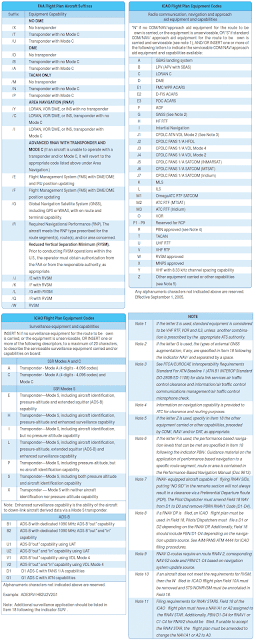 |
| Figure 8. Flight plan equipment codes |
While operating on RNAV segments, pilots are encouraged to use the flight director in lateral navigation mode. RNAV terminal procedures may be amended by ATC issuing radar vectors and/or clearances direct to a waypoint. Pilots should avoid premature manual deletion of waypoints from their active “legs” page to allow for rejoining procedures. While operating on RNAV segments, pilots operating /R aircraft should adhere to any flight manual limitation or operating procedure required to maintain the RNP value specified for the procedure. In 2008, the FAA implemented the use of en route host automation ICAO flight plan (FP) processing for requesting assignment of RNAV SID, Standard Terminal Arrivals (STARs), or RNAV routes U.S. domestic airspace. This is part of a risk reduction strategy for introduction of the En Route Automation Modernization (ERAM) system in October 2008. ERAM also will use ICAO FP processing and as a result aircrews should be aware that as the FAA updates to ERAM the standard FAA flight plan equipment suffix codes will change to the ICAO flight plan equipment suffix codes.
For procedures requiring GPS and/or aircraft approvals requiring GPS, if the navigation system does not automatically alert the flight crew of a loss of GPS, aircraft operators must develop procedures to verify correct GPS operation. If not equipped with GPS, or for multi-sensor systems with GPS that do not alert upon loss of GPS, aircraft must be capable of navigation system updating using DME/ DME or DME/DME/ IRU for type 1 and 2 procedures. AC 90100 may be used as operational guidance for RNAV ODPs. Pilots of FMS-equipped aircraft who are assigned an RNAV DP procedure and subsequently receive a change of runway, transition, or procedure, must verify that the appropriate changes are loaded and available for navigation. [Figures 9 and 10]
Additionally, new waypoint symbols are used in conjunction with RNAV charts. There are two types of waypoints currently in use: fly-by (FB) and fly-over (FO). A FB waypoint typically is used in a position at which a change in the course of procedure occurs. Charts represent them with four-pointed stars. This type of waypoint is designed to allow you to anticipate and begin your turn prior to reaching the waypoint, thus providing smoother transitions. Conversely, RNAV charts show a FO waypoint as a four-pointed star enclosed in a circle. This type of waypoint is used to denote a missed approach point, a missed approach holding point, or other specific points in space that must be flown over. [Figure 11] Pilots should not change any database waypoint type from a FB to FO, or vice versa.
There are specific requirements; however, that must be met before using RNAV procedures. Every RNAV departure chart lists general notes and may include specific equipment and performance requirements, as well as the type of RNAV departure procedure in the chart plan view. New aircraft equipment suffix codes are used to denote capabilities for advanced RNAV navigation for flight plan filing purposes. [Figure 12]
SID Altitudes
SID altitudes can be charted in four different ways. The first are mandatory altitudes, the second, minimum altitudes, the third, maximum altitudes and the fourth is a combination of minimum and maximum altitudes or also referred to as block altitudes. Below are examples of how each will be shown on a SID chart.
Some SIDs may still have “(ATC)” adjacent to a crossing altitude as shown in Figure 13 which implies that the crossing altitude is there to support an ATC requirement. A new charting standard has begun a process to remove, over a period of time, the ATC annotation. The Cowboy Four Departure (RNAV) shown in Figure 14 depicts the new charting standard without ATC annotations. When necessary, ATC may amend or delete SID crossing altitude restrictions; when doing so, ATC assumes responsibility for obstacle clearance until the aircraft is re-established laterally and vertically on the published SID route.
Pilot Responsibility for Use of RNAV Departures
RNAV usage brings with it multitudes of complications as it is being implemented. It takes time to transition, to disseminate information, and to educate current and potential users. As a current pilot using the NAS, you need to have a clear understanding of the aircraft equipment requirements for operating in a given RNP environment. You must understand the type of navigation system installed in your aircraft, and furthermore, you must know how your system operates to ensure that you can comply with all RNAV requirements. Operational information should be included in your AFM or its supplements. Additional information concerning how to use your equipment to its fullest capacity, including “how to” training, may be gathered from your avionics manufacturer. If you are in doubt about the operation of your avionics system and its ability to comply with RNAV requirements, contact the FAA directly through your local Flight Standards District Office (FSDO). RNAV departure procedures are being developed at a rapid pace to provide RNAV capabilities at all airports. With every chart revision cycle, new RNAV departures are being added for small and large airports. These departures are flown in the same manner as traditional navigation-based departures; pilots are provided headings, altitudes, navigation waypoint, and departure descriptions. RNAV SIDs are found in the TPP with traditional departure procedures.
Radar Departures
A radar departure is another option for departing an airport on an IFR flight. You might receive a radar departure if the airport does not have an established departure procedure, if you are unable to comply with a departure procedure, or if you request “No SIDs” as a part of your flight plan. Expect ATC to issue an initial departure heading if you are being radar vectored after takeoff; however, do not expect to be given a purpose for the specific vector heading. Rest assured that the controller knows your flight route and will vector you into position. By nature of the departure type, once you are issued your clearance, the responsibility for coordination of your flight rests with ATC, including the tower controller and, after handoff, the departure controller who will remain with you until you are released on course and allowed to “resume own navigation.”
For all practical purposes, a radar departure is the easiest type of departure to use. It is also a good alternative to a published departure procedure, particularly when none of the available departure procedures are conducive to your flight route. However, it is advisable to always maintain a detailed awareness of your location while you are being radar vectored by ATC. If for some reason radar contact is lost, you will be asked to provide position reports in order for ATC to monitor your flight progress. Also, ATC may release you to “resume own navigation” after vectoring you off course momentarily for a variety of reasons, including weather or traffic.
Upon initial contact, state your aircraft or flight number, the altitude you are climbing through, and the altitude to which you are climbing. The controller will verify that your reported altitude matches that emitted by your transponder. If your altitude does not match, or if you do not have Mode C capabilities, you will be continually required to report your position and altitude for ATC.
The controller is not required to provide terrain and obstacle clearance just because ATC has radar contact with your aircraft. It remains your responsibility until the controller begins to provide navigational guidance in the form of radar vectors. Once radar vectors are given, you are expected to promptly comply with headings and altitudes as assigned. Question any assigned heading if you believe it to be incorrect or if it would cause a violation of a regulation, then advise ATC immediately and obtain a revised clearance.
Diverse Vector Area
ATC may establish a minimum vectoring altitude (MVA) around certain airports. This altitude, based on terrain and obstruction clearance, provides controllers with minimum altitudes to vector aircraft in and around a particular location. However, at times, it may be necessary to vector aircraft below this altitude to assist in the efficient flow of departing traffic. For this reason, an airport may have an established Diverse Vector Area (DVA). This DVA may be established below the MVA or Minimum IFR Altitude (MIA) in a radar environment at the request of Air Traffic. This type of DP meets the TERPs criteria for diverse departures, obstacles and terrain avoidance in which random radar vectors below the MVA/MIA may be issued to departing traffic.
The existence of a DVA will be noted in the Takeoff Minimums and Obstacle Departure Procedures section of the U.S. Terminal Procedure Publication (TPP). The Takeoff Departure procedure will be listed first, followed by any applicable DVA. Pilots should be aware that Air Traffic facilities may utilize a climb gradient greater than the standard 200 ft/NM within a DVA. This information will be identified in the DVA text for pilot evaluation against the aircraft’s performance. Pilots should note that the DVA has been assessed for departures which do not follow a specified ground track, but will remain within the specified area. ATC may also vector an aircraft off a previously assigned DP. In all cases, the minimum 200 ft/NM climb gradient is assumed unless a higher is specified on the departure, and obstacle clearance is not provided by ATC until the controller begins to provide navigational guidance (vectors). Lastly, pilots should understand ATC instructions take precedence over an ODP [Figure 15]
Visual Climb Over Airport (VCOA)
A visual climb over airport (VCOA) is a departure option for an IFR aircraft, operating in VMC equal to or greater than the specified visibility and ceiling, to visually conduct climbing turns over the airport to the published “climb-to” altitude from which to proceed with the instrument portion of the departure. A VCOA is a departure option developed when obstacles farther than 3 SM from the airport require a CG of more than 200 ft/NM.
These procedures are published in the Take-Off Minimums and (Obstacle) Departure Procedures section of the TPP. [Figure 16] Prior to departure, pilots are required to notify ATC when executing the VCOA.
Noise Abatement Procedures
As the aviation industry continues to grow and air traffic increases, so does the population of people and businesses around airports. As a result, noise abatement procedures have become commonplace at most of the nation’s airports. 14 CFR Part 150 specifies the responsibilities of the FAA to investigate the recommendations of the airport operator in a noise compatibility program and approve or disapprove the noise abatement suggestions. This is a crucial step in ensuring that the airport is not unduly inhibited by noise requirements and that air traffic workload and efficiency are not significantly impacted, all while considering the noise problems addressed by the surrounding community.
While most DPs are designed for obstacle clearance and workload reduction, there are some SIDs that are developed solely to comply with noise abatement requirements. Portland International Jetport is an example of an airport where a SID was created strictly for noise abatement purposes as noted in the DP. [Figure 16] Typically, noise restrictions are incorporated into the main body of the SID. These types of restrictions require higher departure altitudes, larger climb gradients, reduced airspeeds, and turns to avoid specific areas. Noise restrictions may also be evident during a radar departure. ATC may require you to turn away from your intended course or vector you around a particular area. While these restrictions may seem burdensome, it is important to remember that it is your duty to comply with written and spoken requests from ATC.
Additionally, when required, departure instructions specify the actual heading to be flown after takeoff, as is the case in Figure 17 under the departure route description, “Climb via heading 112 degrees…” Some existing procedures specify, “Climb runway heading.”Over time, both of these departure instructions will be updated to read, “Climb heading 112 degrees….” Runway heading is the magnetic direction that corresponds with the runway centerline extended (charted on the airport diagram), not the numbers painted on the runway. Pilots cleared to “fly or maintain runway heading” are expected to fly or maintain the published heading that corresponds with the extended centerline of the departure runway (until otherwise instructed by ATC), and are not to apply drift correction (e.g., RWY 11, actual magnetic heading of the runway centerline 112.2 degrees, “fly heading 112 degrees”). In the event of parallel departures, this prevents a loss of separation caused by only one aircraft applying a wind drift.

