There are three fixed route systems established for air navigation purposes. They are the Federal airway consisting of VOR (low victor airways, high jet routes), NDB (low or medium frequency) and the RNAV route system. To the extent possible, these route systems are aligned in an overlying manner to facilitate transition between each. The majority of the airways are made up of victor airways, jet routes, and RNAV, but some low/ medium frequency (L/MF) airways and routes are still being used in Alaska and one other that is located off the coast of North Carolina and is called Green 13 (G13). [Figure 1]
 |
| Figure 1. Low frequency airway G13 |
Airway/Route Depiction
IFR en route charts show all IFR radio NAVAIDs that have been flight-checked by the FAA and are operational. The FAA, Aeronautical Information Services publishes and distributes U.S. Government Civil Aeronautical Charts and flight information publications. IFR en route navigation information is provided on three charts: IFR en route low altitude chart, IFR en route high altitude chart, and Terminal Area Chart (TAC). [Figure 2A and B]
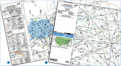 |
| Figure 2. IFR en route low altitude (left) and high altitude (right) charts |
IFR En Route Low Altitude Chart
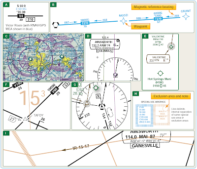
En route low altitude charts provide aeronautical information for navigation under IFR conditions below 18,000 feet MSL. Low altitude charts [Figure 3] include the following information:
 |
| Figure 3. Information found on en route low altitude charts |
- Airways [Figure 3A]
- RNAV routes [Figure 3B]
- Limits of controlled airspace [Figure 3C]
- VHF radio aids to navigation (frequency, identification, channel, geographic coordinates) [Figure 3D]
- Airports that have an instrument approach procedure or a minimum 3,000 foot hard surface runway [Figure 3E]
- Off-route obstruction clearance altitudes (OROCA) [Figure 3F]
- Reporting points [Figure 3G]
- Special use airspace areas [Figure 3H]
- Military training routes [Figure 3I]
IFR aeronautical charts depict VOR airways (airways based on VOR or VORTAC NAVAIDs) in black, identified by a “V” (Victor) followed by the route number (e.g., V12). [Figure 4] LF/MF airways (airways based on LF/MF NAVAIDs) are sometimes referred to as colored airways because they are identified by color name and number (e.g., Amber One, charted as A1). Green and red airways are plotted east and west, and amber and blue airways are plotted north and south. Regardless of their color identifier, LF/MF airways are depicted in brown. [Figure 5]
 |
| Figure 4. Victor airways |
 |
| Figure 5. LF/MF airways |
Airway/route data, such as the airway identifications, bearings or radials, mileages, and altitude (e.g., MEA), minimum obstacle clearance altitude (MOCA), and MAA, are shown aligned with the airway and in the same color as the airway. [Figure 4]
All airways/routes that are predicated on VOR or VORTAC NAVAIDs are defined by the outbound radial from the NAVAID. Airways/routes that are predicated on LF/MF NAVAIDs are defined by the inbound bearing.
New low altitude RNAV routes have been created by the FAA. RNAV routes provide more direct routing for IFR aircraft and enhance the safety and efficiency of the NAS. In order to utilize these routes, aircraft must be equipped with IFR approved GNSS. In Alaska, when using RNAV routes, the aircraft must be equipped with Technical Standing Order (TSO)-145a and 146a equipment.
Low altitude RNAV only routes are identified by the letter “T” prefix, followed by a three digit number (T-200 to T-500). RNAV routes are depicted in aeronautical blue, as well as the RNAV route data, which includes the following [Figure 6]:
 |
| Figure 6. Low altitude RNAV routes |
- Route line
- Identification boxes
- Mileages
- Waypoints
- Waypoint names
- Magnetic reference bearings
- MEAs
Magnetic reference bearings are shown originating from a waypoint, fix/reporting point, or NAVAID. A GNSS MEA for each segment is established to ensure obstacle clearance and communications reception. All MEAs are identified with a “G” suffix. [Figure 7]
 |
| Figure 7. Low altitude RNAV route data |
Joint Victor/RNAV routes are depicted using black for the victor airways and blue for the RNAV routes, and the identification boxes for each are shown adjacent to one another. Magnetic reference bearings are not shown. MEAs are stacked in pairs or in two separate columns, GNSS and Victor. On joint routes, or victor routes, RNAV specific information is printed in blue. [Figure 8]
 |
| Figure 8. Joint Victor/RNAV airway |
IFR En Route High Altitude Chart
En route high altitude charts provide aeronautical information for navigation under IFR conditions at and above FL 180. [Figure 9] High altitude charts include the following information:
 |
| Figure 9. IFR en route high altitude chart |
- Jet route structure
- RNAV Q-routes
- VHF radio aids to navigation (frequency, ID, channel, geographic coordinates)
- Selected airports
- Reporting points
- Navigation reference system (NRS) waypoints [Figure 10]
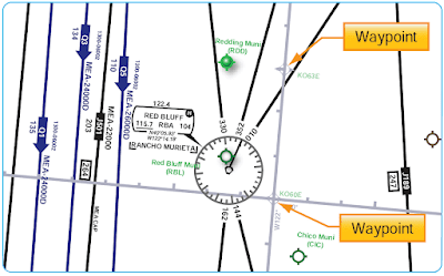 |
| Figure 10. Navigation reference system (NRS) waypoints |
Jet routes are depicted in black with a “J” identifier followed by the route number (e.g., “J12”) and are based on VOR or VORTAC NAVAIDs. [Figure 11] RNAV “Q” Route MEAs are shown when other than 18,000 feet. [Figure 12] MEAs for GNSS RNAV aircraft are identified with a “G” suffix. MEAs for DME/DME/IRU RNAV aircraft do not have a “G” suffix. All RNAV routes and associated data is charted in aeronautical blue and magnetic reference bearings are shown originating from a waypoint, fix/reporting point, or NAVAID. When joint Jet/RNAV routes are depicted, the route identification boxes are located adjacent to each other with the route charted in black. [Figure 13] With the exception of “Q” routes in the Gulf of Mexico, GNSS or DME/DME/IRU RNAV equipment is required along with radar monitoring capabilities. For aircraft that have DME/DME/IRU RNAV equipment, refer to the CS for specific DME information.
 |
| Figure 11. High altitude jet routes |
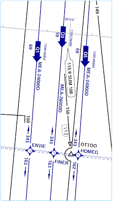 |
| Figure 12. MEAs on RNAV (Q) routes |
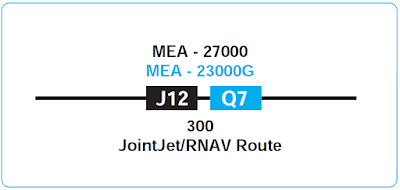 |
| Figure 13. Joint jet/RNAV routes |
VHF Airways
Victor airways are a system of established routes that run along specified VOR radials, from one VOR station to another. The purpose is to make flight planning easier and they help ATC to organize and regulate the air traffic flow. Almost all commercial flights are routed along these airways but they are available for use by any pilot provided that the proper altitudes are employed.
Victor Airway Navigation Procedures
The procedure for getting established on a victor airway is to either fly directly to a nearby VOR or to intercept an airway radial along the route of flight. Once the pilot is established on an airway, it is important to follow the procedures and guidelines put in place to ensure air traffic separation and optimal safety on the airway. When using victor airways for navigation, procedures do not allow the pilot to jump from one VOR to another, but must navigate from one to the next by using the alternating outbound/ inbound procedure of linking VORs. For example, when departing from Zanesville VOR on V-214, the pilot selects the 090° radial with a FROM indication on the course deviation indicator (CDI) and should correct as necessary to continuously maintain track on the centerline of the airway. [Figure 14] The pilot should continue on this course until it is time to change over to the inbound course to the Bellaire VOR.
 |
| Figure 14. Zanesville VOR/Victor Airway 214 |
LF/MF Airways
The basic LF/MF airway width is 4.34 nautical miles (NM) on each side of the centerline; the width expands by five degrees when the distance from the facility providing course guidance is greater than 49.66 NM. [Figure 15]
 |
| Figure 15. LF/MR airway width |
En Route Obstacle Clearance Areas
All published routes in the NAS are based on specific obstacle clearance criteria. An understanding of en route obstacle clearance areas helps with SA and may help avoid controlled flight into terrain (CFIT). Obstacle clearance areas for the en route phase of flight are identified as primary, secondary, and turning areas.
The primary and secondary area obstacle clearance criteria, airway and route widths, and the ATC separation procedures for en route segments are a function of safety and practicality in flight procedures. These flight procedures are dependent upon the pilot, the aircraft, and the navigation system being used, resulting in a total VOR system accuracy factor along with an associated probability factor. The pilot/aircraft information component of these criteria includes pilot ability to track the radial and the flight track resulting from turns at various speeds and altitudes under different wind conditions. The navigation system information includes navigation facility radial alignment displacement, transmitter monitor tolerance, and receiver accuracy. All of these factors were considered during development of en route criteria. From this analysis, the computations resulted in a total system accuracy of ±4.5° 95 percent of the time and ±6.7° 99 percent of the time. The 4.5° value became the basis for primary area obstacle clearance criteria, airway and route widths, and the ATC separation procedures. The 6.7° value provides secondary obstacle clearance area dimensions.
Primary and Secondary En Route Obstacle Clearance Areas
The primary obstacle clearance area has a protected width of 8 NM with 4 NM on each side of the centerline. The primary area has widths of route protection based upon system accuracy of a ±4.5° angle from the NAVAID. These 4.5° lines extend out from the NAVAID and intersect the boundaries of the primary area at a point approximately 51 NM from the NAVAID. Ideally, the 51 NM point is where pilots would change over from navigating away from the facility, to navigating toward the next facility, although this ideal is rarely achieved. [Figure 16]
 |
| Figure 16. Primary obstacle clearance area |
If the distance from the NAVAID to the change-over point (COP) is more than 51 NM, the outer boundary of the primary area extends beyond the 4 NM width along the 4.5° line when the COP is at midpoint. This means the primary area, along with its obstacle clearance criteria, is extended out into what would have been the secondary area. Additional differences in the obstacle clearance area result in the case of the effect of an offset COP or dogleg segment. For protected en route areas, the minimum obstacle clearance in the primary area, not designated as mountainous under 14 CFR Part 95—IFR altitude, is 1,000 feet over the highest obstacle. [Figure 17] The secondary obstacle clearance area extends along a line 2 NM on each side of the primary area. Navigation system accuracy in the secondary area has widths of route protection of a ±6.7° angle from the NAVAID. These 6.7° lines intersect the outer boundaries of the secondary areas at the same point as primary lines, 51 NM from the NAVAID. If the distance from the NAVAID to the COP is more than 51 NM, the secondary area extends along the 6.7° line when the COP is at mid-point. [Figure 18] In all areas, mountainous and non-mountainous, obstacles that are located in secondary areas are considered as obstacles to air navigation if they extend above the secondary obstacle clearance plane. This plane begins at a point 500 feet above the obstacles (natural or man-made) upon which the primary obstacle clearance area is based, and slants upward at an angle that causes it to intersect the outer edge of the secondary area at a point 500 feet higher. [Figure 19]
 |
| Figure 17. Non-mountainous obstacle clearance in the primary area |
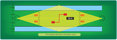 |
| Figure 18. Secondary obstacle clearance area |
 |
| Figure 19. Primary and secondary obstacle clearance area |
Changeover Points
When flying airways, pilots normally change frequencies midway between NAVAIDs, although there are times when this is not practical. If the navigation signals cannot be received from the second VOR at the midpoint of the route, a COP is depicted and shows the distance in NM to each NAVAID. [Figure 20] COPs indicate the point where a frequency change is necessary to receive course guidance from the facility ahead of the aircraft instead of the one behind. These COPs divide an airway or route segment and ensure continuous reception of navigation signals at the prescribed minimum en route IFR altitude. They also ensure that other aircraft operating within the same portion of an airway or route segment receive consistent azimuth signals from the same navigation facilities regardless of the direction of flight.
 |
| Figure 20. Changeover points |
Where signal coverage from two VORs overlaps at the MEA, the COP normally is designated at the midpoint. Where radio frequency interference or other navigation signal problems exist, the COP is placed at the optimum location, taking into consideration the signal strength, alignment error, or any other known condition that affects reception. The COP has an effect on the primary and secondary obstacle clearance areas. On long airway or route segments, if the distance between two facilities is over 102 NM and the COP is placed at the midpoint, the system accuracy lines extend beyond the minimum widths of 8 and 12 NM, and a flare or spreading outward results at the COP. [Figure 21] Offset COP and dogleg segments on airways or routes can also result in a flare at the COP.
 |
| Figure 21. Changeover point effect on long airway or route segment |
Direct Route Flights
Direct route flights are flights that are not flown on the radials or courses of established airways or routes. Direct route flights must be defined by indicating the radio fixes over which the flight passes. Fixes selected to define the route should be those over which the position of the aircraft can be accurately determined. Such fixes automatically become compulsory reporting points for the flight, unless advised otherwise by ATC. Only those NAVAIDs established for use in a particular structure (i.e., in the low or high structures) may be used to define the en route phase of a direct flight within that altitude structure.
Figure 22 shows a straight line on a magnetic course from SCRAN intersection of 270° direct to the Fort Smith Regional Airport in Arkansas that passes just north of restricted areas R-2401A and B and R-2402. Since the airport and the restricted areas are precisely plotted, there is an assurance that you will stay north of the restricted areas. From a practical standpoint, it might be better to fly direct to the Wizer NDB. This route goes even further north of the restricted areas and places you over the final approach fix to Runway 25 at Fort Smith.
 |
| Figure 22. Direct route navigation |
The azimuth feature of VOR aids and the azimuth and distance (DME) features of VORTAC and TACAN aids are assigned certain frequency protected areas of airspace that are intended for application to established airway and route use and to provide guidance for planning flights outside of established airways or routes. These areas of airspace are expressed in terms of cylindrical service volumes of specified dimensions called class limits or categories.
An operational service volume has been established for each class in which adequate signal coverage and frequency protection can be assured. To facilitate use of VOR, VORTAC, or TACAN aids, consistent with their operational service volume limits, pilot use of such aids for defining a direct route of flight in controlled airspace should not exceed the following:
- Operations above FL 450—use NAVAIDs not more than 200 NM apart. These aids are depicted on en route high altitude charts.
- Operation off established routes from 18,000 feet MSL to FL 450—use NAVAIDs not more than 260 NM apart. These aids are depicted on en route high altitude charts.
- Operation off established airways below 18,000 feet MSL—use NAVAIDs not more than 80 NM apart. These aids are depicted on en route low altitude charts.
- Operation off established airways between 14,500 feet MSL and 17,999 feet MSL in the conterminous United States—(H) facilities not more than 200 NM apart may be used.
Increasing use of self-contained airborne navigational systems that do not rely on the VOR/VORTAC/TACAN system has resulted in pilot requests for direct routes that exceed NAVAID service volume limits. These direct route requests are approved only in a radar environment with approval based on pilot responsibility for navigation on the authorized direct route. Radar flight following is provided by ATC for ATC purposes. At times, ATC initiates a direct route in a radar environment that exceeds NAVAID service volume limits. In such cases, ATC provides radar monitoring and navigational assistance as necessary.
When filing for a direct route flight, airway or jet route numbers, appropriate to the stratum in which operation is conducted, may also be included to describe portions of the route to be flown. The following is an example of how a direct route flight would be written.
MDW V262 BDF V10 BRL STJ SLN GCK
Spelled out: from Chicago Midway Airport via Victor 262 to Bradford, Victor 10 to Burlington, Iowa, direct St. Joseph, Missouri, direct Salina, Kansas, direct Garden City, Kansas.
Note: When route of flight is described by radio fixes, the pilot is expected to fly a direct course between the points named.
Pilots should keep in mind that they are responsible for adhering to obstruction clearance requirements on those segments of direct routes that are outside of controlled airspace. The MEAs and other altitudes shown on low altitude IFR en route charts pertain to those route segments within controlled airspace, and those altitudes may not meet obstruction clearance criteria when operating off those routes.
Published RNAV Routes
Published RNAV routes are fixed, permanent routes that can be flight planned and flown by aircraft with RNAV capability. These are being expanded worldwide as new RNAV routes are developed, and existing charted, conventional routes are being designated for RNAV use. It is important to be alert to the rapidly changing application of RNAV techniques being applied to conventional en route airways. Published RNAV routes may potentially be found on any en route chart. The published RNAV route designation may be obvious, or, on the other hand, RNAV route designations may be less obvious, as in the case where a published route shares a common flight track with a conventional airway.
Note: The use of RNAV is dynamic and rapidly changing; therefore, en route charts are continuously being updated for information changes, and you may find some differences between charts.
Basic designators for air traffic service (ATS) routes and their use in voice communications have been established. One of the main purposes of a system of route designators is to allow both pilots and ATC to make unambiguous reference to RNAV airways and routes. Basic designators for ATS routes consist of a maximum of five, and in no case to exceed six, alpha/numeric characters in order to be usable by both ground and airborne automation systems. The designator indicates the type of the route, such as high/low altitude, specific airborne navigation equipment requirements, such as RNAV, and the aircraft type using the route primarily and exclusively. The basic route designator consists of one or two letter(s) followed by a number from 1 to 999.
Composition of Designators
The prefix letters that pertain specifically to RNAV designations are included in the following list:
1. Basic designator consists of one letter of the alphabet followed by a number 1 to 999. The letters may be:
- A, B, G, R – for routes that form part of the regional networks of ATS route and are not RNAV routes;
- L, M, N, P- for RNAV routes that form part of the regional networks of ATS routes;
- H, J, V, W – for routes that do not form part of the regional networks of ATS routes and are not RNAV routes;
- Q, T, Y, Z- for RNAV routes that do not form part of the regional networks of ATS routes.
2. Where applicable, one plementary letter must be added as a prefix to the basic designator as follows:
- K- to indicate to a low-level route established for use primarily by helicopters;
- U- to indicate that the route or portion thereof is established in the upper airspace;
- S- to indicate a route established exclusively for use by supersonic aircraft during acceleration/deceleration and while in supersonic flight.
3. Where applicable, a supplementary letter may be added after basic designator of the ATS route as a suffix as follows:
- F—to indicate that on the route or portion thereof advisory service only is provided;
- G—to indicate that on the route or portion thereof flight information services only is provided;
- Y—for RNP 1 routes at and above FL 200 to indicate that all turns on the route between 30° and 90° must be made within the tolerance of a tangential arc between the straight leg segments defined with a radius of 22.5 NM;
- Z—for RNP 1 routes at and below FL 190 to indicate that all turns on the route between 30° and 90° should be made within the tolerance of a tangential arc between the straight leg segments defined with a radius of 15 NM.
Note: RNAV-Q-routes require en route RNAV2, corresponding NAV/E2 code and PBN/C1-C4 based on navigation system update source.
Use of Designator in Communications
In voice communications, the basic letter of a designator should be spoken in accordance with the International Civil Aviation Organization (ICAO) spelling alphabet. Where the prefixes K, U or S, previously mentioned, are used in voice communications, they should be pronounces as:
- K- Kopter
- U- Upper, as in the English language
- S- Supersonic
Where suffixes F,G, Y or Z specifies in above, are used the flight crew should not be requires to use them in voice communications. Below is an example of how the letters and number are spoken.
- A11- Alpha Eleven
- UR5- Upper Romeo Five
- KB34- Kopter Bravo Thirty Four
- UW456- Upper Whiskey Four Fifty Six
The en route chart excerpt depicts three published RNAV jet routes: J804R, J888R, and J996R. [Figure 23] The R suffix is a supplementary route designator denoting an RNAV route. The overlapping symbols for the AMOTT intersection and waypoint indicate that AMOTT can be identified by conventional navigation or by latitude and longitude coordinates. Although coordinates were originally included for aircraft equipped with an inertial navigation system (INS), they are now a good way to cross check between the coordinates on the chart and in the flight management system (FMS) or global positioning system (GPS) databases to ensure you are tracking on your intended en route course. The AMOTT RNAV waypoint includes bearing and distance from the Anchorage VORTAC.
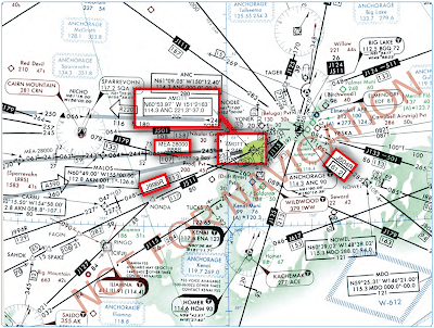 |
| Figure 23. Published RNAV jet routes |
Random RNAV Routes
Random RNAV routes are direct routes that are based on RNAV capability between waypoints defined in terms of latitude or longitude coordinates, degree-distance fixes, or offsets from established routes or airways at a specified distance and direction. Radar monitoring by ATC is required on all random RNAV routes. Random RNAV routes can only be approved in a radar environment. Factors that are considered by ATC when approving random RNAV routes include the capability to provide radar monitoring and compatibility with traffic volume and flow. ATC radar monitor each flight; however, navigation on the random RNAV route is the responsibility of the pilot.
Pilots flying aircraft that are equipped with approved area navigation equipment may file for RNAV routes throughout the NAS and may be filed for in accordance with the following procedures:
- File airport-to-airport flight plans.
- File the appropriate RNAV capability certification suffix in the flight plan.
- Plan the random route portion of the flight plan to begin and end over appropriate arrival and departure transition fixes or appropriate NAVAIDs for the altitude stratum within which the flight is conducted. The use of normal preferred DPs and STAR, where established, is recommended.
- File route structure transitions to and from the random route portion of the flight.
- Define the random route by waypoints. File route description waypoints by using degree distance fixes based on navigational aids that are appropriate for the altitude stratum.
- File a minimum of one route description waypoint for each ARTCC through whose area the random route is flown. These waypoints must be located within 200 NM of the preceding center’s boundary.
- File an additional route description waypoint for each turnpoint in the route.
- Plan additional route description waypoints as required to ensure accurate navigation via the filed route of flight. Navigation is the pilot’s responsibility unless ATC assistance is requested.
- Plan the route of flight so as to avoid prohibited and restricted airspace by 3 NM unless permission has been obtained to operate in that airspace and the appropriate ATC facilities are advised.
Note: To be approved for use in the NAS, RNAV equipment must meet the appropriate system availability, accuracy, and airworthiness standards. For additional guidance on equipment requirements, see Advisory Circular (AC) 20-138C, Airworthiness Approval of Positioning and Navigation Systems. For airborne navigation database, see AC 90-105, Approval Guidance for RNP Operations and Barometric Vertical Navigation in the U.S. National Airspace System.
Pilots flying aircraft that are equipped with latitude/ longitude coordinate navigation capability, independent of VOR/ TACAN references, may file for random RNAV routes at and above FL 390 within the conterminous United States using the following procedures:
1. File airport-to-airport flight plans prior to departure.
2. File the appropriate RNAV capability certification suffix in the flight plan.
3. Plan the random route portion of the flight to begin and end over published departure/arrival transition fixes or appropriate NAVAIDs for airports without published transition procedures. The use of preferred departure and arrival routes, such as DP and STAR where established, is recommended.
4. Plan the route of flight so as to avoid prohibited and restricted airspace by 3 NM unless permission has been obtained to operate in that airspace and the appropriate ATC facility is advised.
5. Define the route of flight after the departure fix, including each fix (turnpoint) and the arrival fix for the destination airport in terms of latitude/longitude coordinates plotted to the nearest minute or in terms of Navigation Reference System (NRS) waypoints. For latitude/longitude filing, the arrival fix must be identified by both the latitude/ longitude coordinates and a fix identifier as shown in the example below.
MIA1 SRQ2 3407/106153 3407/11546
TNP4 LAX5 1Departure
airport
2Departure fix
3Intermediate
fix (turning point)
4Arrival fix
5Destination
airport
Or:
ORD1 IOW2 KP49G3 KD34U4 KL16O5 OAL6 MOD27 SFO8
1Departure
airport
2Transition
fix (pitch point)
3Minneapolis
ARTCC waypoint
4Denver ARTCC
waypoint
5Los Angeles
ARTCC waypoint (catch point)
6Transition
fix
7Arrival
8Destination
airport
6. Record latitude/longitude coordinates by four figures describing latitude in degrees and minutes followed by a solidus and five figures describing longitude in degrees and minutes.
7. File at FL 390 or above for the random RNAV portion of the flight.
8. Fly all routes/route segments on Great Circle tracks.
9. Make any in-flight requests for random RNAV clearances or route amendments to an en route ATC facility.
Off-Airway Routes
14 CFR Part 95 prescribes altitudes governing the operation of aircraft under IFR on Federal airways, jet routes, RNAV low or high altitude routes, and other direct routes for which a MEA is designated. In addition, it designates mountainous areas and COPs. Off-airway routes are established in the same manner and in accordance with the same criteria as airways and jet routes. If a pilot flies for a scheduled air carrier or operator for compensation or hire, any requests for the establishment of off-airway routes are initiated by the company through the principal operations inspector (POI) who works directly with the company and coordinates FAA approval. Air carrier authorized routes should be contained in the company’s Operations Specifications (OpSpecs) under the auspices of the air carrier operating certificate. [Figure 24]
 |
| Figure 24. Excerpt of authorized areas of en route operation |
Off-airway routes predicated on public navigation facilities and wholly contained within controlled airspace are published as direct Part 95 routes. Off-airway routes predicated on privately owned navigation facilities or not contained wholly within controlled airspace are published as off-airway non-Part 95 routes. In evaluating the adequacy of off-airway routes, the following items are considered: the type of aircraft and navigation systems used; proximity to military bases, training areas, low level military routes; and the adequacy of communications along the route.
Commercial operators planning to fly off-airway routes should have specific instructions in the company’s OpSpecs that address en route limitations and provisions regarding en route authorizations to use the GPS or other RNAV systems in the NAS. The company’s manuals and checklists should include practices and procedures for long-range navigation and training on the use of long range navigation equipment. Minimum equipment lists (MELs) and maintenance programs must address the long range navigation equipment. Examples of other selected areas requiring specialized en route authorization include the following:
- Class I navigation in the United States Class A airspace using area of long range navigation system.
- Class II navigation using multiple long range navigation systems.
- Operations in central East Pacific airspace.
- North Pacific operations.
- Operations within North Atlantic (NAT) minimum navigation performance specifications (MNPS) airspace.
- Operations in areas of magnetic unreliability.
- North Atlantic operation (NAT/OPS) with two engine aircraft under 14 CFR Part 121.
- Extended range operations (ER-OPS) with two engine aircraft under 14 CFR Part 121.
- Special fuel reserves in international operations.
- Planned in-flight re-dispatch or re-release en route.
- Extended over water operations using a single long-range communication system.
- Operations in reduced vertical separation minimum (RVSM) airspace.
Off-Route Obstruction Clearance Altitude
An off-route obstruction clearance altitude (OROCA) is an off-route altitude that provides obstruction clearance with a 1,000-foot buffer in non-mountainous terrain areas and a 2,000-foot buffer in designated mountainous areas within the United States. This altitude may not provide signal coverage from ground-based NAVAIDs, ATC radar, or communications coverage. OROCAs are intended primarily as a pilot tool for emergencies and SA. OROCAs depicted on en route charts do not provide the pilot with an acceptable altitude for terrain and obstruction clearance for the purposes of off-route, random RNAV direct flights in either controlled or uncontrolled airspace. OROCAs are not subject to the same scrutiny as MEAs, minimum vectoring altitude (MVAs), MOCAs, and other minimum IFR altitudes. Since they do not undergo the same obstruction evaluation, airport airspace analysis procedures, or flight inspection, they cannot provide the same level of confidence as the other minimum IFR altitudes.
When departing an airport VFR intending to or needing to obtain an IFR clearance en route, you must be aware of the position of your aircraft relative to terrain and obstructions. When accepting a clearance below the MEA, MIA, MVA, or the OROCA, you are responsible for your own terrain/ obstruction clearance until reaching the MEA, MIA, or MVA. If unable to visually maintain terrain/obstruction clearance, pilots should advise ATC and state intentions of the flight. [Figure 25]
 |
| Figure 25. Off-route obstacle clearance altitude |
For all random RNAV flights, there needs to be at least one waypoint in each ARTCC area through which you intend to fly. One of the biggest problems in creating an RNAV direct route is determining if the route goes through special use airspace. For most direct routes, the chances of going through prohibited, restricted, or special use airspace are good. In the United States, all direct routes should be planned to avoid prohibited or restricted airspace by at least 3 NM. If a bend in a direct route is required to avoid special use airspace, the turning point needs to be part of the flight plan. Two of the most prominent long range navigation systems today include FMS with integrated GPS and stand-alone GPS. The following example is a simplified overview showing how the RNAV systems might be used to fly a random RNAV route.
Shown in Figure 26, the aircraft is northeast of Tuba City VORTAC at FL 200 using RNAV (showing both GPS and FMS), RNAV direct on a southwesterly heading to Lindbergh Regional Airport in Winslow. As the pilot is monitoring his or her position and cross-checking the avionics against the high altitude en route chart, he or she receives a company message instructing to divert to Las Vegas, requiring a change in the flight plan as highlighted on the depicted chart excerpt.
 |
| Figure 26. Random RNAV route |
During the flight deck review of the high and low altitude en route charts, the pilot determines that the best course of action is to fly direct to the MIRAJ waypoint, 28 DME northeast of the Las Vegas VORTAC on the 045° radial. This places the aircraft 193 NM out on a 259° magnetic course inbound, and may help to avoid diverting north, allowing to bypass the more distant originating and intermediate fixes feeding into Las Vegas. The pilot requests an RNAV random route clearance direct MIRAJ to expedite the flight. Denver Center comes back with the following amended flight plan and initial clearance into Las Vegas:
“Marathon five sixty four, turn right heading two six zero, descend and maintain one six thousand, cleared present position direct MIRAJ.”
The latitude and longitude coordinates of the aircraft’s present position on the high altitude chart is N36 19.10 and W110 40.24 as the course is changed. Notice the GPS moving map (upper left), the FMS control display unit (below the GPS), and FMS map mode navigation displays (to the right of the GPS) as the flight is rerouted to Las Vegas. For SA, the pilot makes note that the altitude is well above any of the OROCAs on the direct route as the flight arrives in the Las Vegas area using the low altitude chart.
Monitoring of Navigation Facilities
VOR, VORTAC, and instrument landing system (ILS) facilities, as well as most NDBs and marker beacons installed by the FAA, are provided with an internal monitoring feature. Internal monitoring is provided at the facility through the use of equipment that causes a facility shutdown if performance deteriorates below established tolerances. A remote status indicator also may be provided through the use of a signal-sampling receiver, microwave link, or telephone circuit. Older FAA NDBs and some non-Federal NDBs do not have the internal feature, and monitoring is accomplished by manually checking the operation at least once each hour. FAA facilities, such as automated flight service stations (AFSSs) and ARTCCs/sectors, are usually the control point for NAVAID facility status. Pilots can query the appropriate FAA facility if they have questions in flight regarding NAVAID status, in addition to checking NOTAMs prior to flight, since NAVAIDs and associated monitoring equipment are continuously changing.
Navigational Gaps
A navigational course guidance gap, referred to as an MEA gap, describes a distance along an airway or route segment where a gap in navigational signal coverage exists. The navigational gap may not exceed a specific distance that varies directly with altitude, from 0 NM at sea level to 65 NM at 45,000 feet MSL and not more than one gap may exist in the airspace structure for the airway or route segment. Additionally, a gap usually does not occur at any airway or route turning point. To help ensure the maximum amount of continuous positive course guidance available when flying, there are established en route criteria for both straight and turning segments. Where large gaps exist that require altitude changes, MEA “steps” may be established at increments of not less than 2,000 feet below 18,000 feet MSL, or not less than 4,000 feet at 18,000 MSL and above, provided that a total gap does not exist for the entire segment within the airspace structure. MEA steps are limited to one step between any two facilities to eliminate continuous or repeated changes of altitude in problem areas. The allowable navigational gaps pilots can expect to see are determined, in part, by reference to the graph depicted in Figure 27. Notice the en route chart excerpt depicting that the MEA is established with a gap in navigation signal coverage northwest of the Carbon VOR/DME on V134. At the MEA of 13,000, the allowable navigation course guidance gap is approximately 18.5 NM, as depicted in Figure 27. The navigation gap area is not identified on the chart by distances from the navigation facilities. Proper flight planning will help pilots prepare for MEA gaps by insuring that appropriate maps are available as they may need to dead reckon through the gap. Calculating the ground track (with adjustments for winds) before and after the gap will also help to stay on course when navigational course guidance is not available.
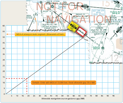 |
| Figure 27. Navigational course guidance gaps |
NAVAID Accuracy Check
The CFRs and good judgment dictate that the equipment of aircraft flying under IFR be within a specified tolerance before taking off. When approved procedures are available, they should be used for all equipment inspections.
VOR Accuracy
VOR accuracy can be checked by using any of the following methods: VOR test facility signal (VOT), VOR checkpoint signs, dual VOR check, or airborne VOR check.
VOT
The VOT is an approved test signal and is located on an airport. This enables the pilot to check the VOR accuracy from the flight deck before takeoff. Listed below are the steps used for a VOT:
- Tune the VOR receiver to the VOT frequency. VOT frequencies can be found in the CS. [Figure 28] These frequencies are coded with a series of Morse code dots or a continuous 1020-cycle tone.
- On the VOR, set the course selector to 0° and the track bar (TB) indicator should read center. The TOFROM indicator should read FROM.
- Set the course selector to 180° and the TO-FROM indicator should read TO and the TB should then be centered.
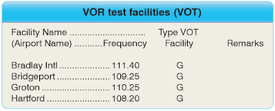 |
| Figure 28. VOR test facilities (VOT) frequencies |
Note: Determining the exact error in the receiver is done by turning the track selector until the TB is centered and noting the degrees difference between 180° or 0°. The maximum bearing error with the VOT system check is plus or minus 4° and apparent errors greater than 4° indicate that the VOR receiver is beyond acceptable tolerance.
VOR Checkpoint Signs
Many aerodromes have VOR checkpoint signs that are located beside the taxiways. [Figure 29] These signs indicate the exact point on the aerodrome that there is sufficient signal strength from a VOR to check the aircraft’s VOR receiver against the radial designated on the sign. Listed below are the steps to use at a VOR checkpoint:
 |
| Figure 29. VOR checkpoint signs |
- Tune the proper VOR frequency.
- Identify the VOR frequency.
- Set the published radial on the course deviation indicator (CDI).
- Confirm that the TB is centered. To
- Check the needle sensitivity by changing the omnibearing select (OBS) 10° each way.
- Set the reciprocal of the radial and check the TO-FROM flag change.
- The maximum permissible difference between aircraft equipment and the designated radial is 4° and 0.5 NM of the posted distance.
Dual VOR Check
If a VOT or VOR checkpoint is not available and the aircraft is equipped with dual VORs, the equipment may be checked against one another by tuning both sets to the VOR facility at the same time and noting the indicated bearings to that station. [Figure 30] A difference greater than 4° between the two VORs indicates that one of the receivers may be out of tolerance.
 |
| Figure 30. Instrument panel with dual VORs |
Airborne VOR Check
VOR equipment can also be checked for accuracy while in flight by flying over a fix or landmark located on a published radial and noting the indicated radial. Variances of more than 6° from the published radial should be considered out f tolerance and not be used for IFR navigation.
NDB Accuracy Check
The pilot must identify an NDB before using it for navigation, and continuously monitor it while using it for an instrument approach. The lack of an IDENT may indicate that the NDB is out of service, even though it may still be transmitting (for instance for maintenance or test purposes). If an incorrect IDENT is heard, then the NDB should not be used.
RNAV Accuracy Check
RNAV accuracy checks may differ depending on the different type of equipment and manufacturer. When available, all written procedures should be followed.
Below is a list of generic checks that should be used when checking the accuracy of the system prior to flight.
- System initialization—pilots should confirm that the navigation database is current and verify that the aircrafts present position has been entered correctly.
- Active flight plan check—the active flight plan should be checked by comparing the aeronautical charts, departure and arrival procedures, and other applicable documents with the map display.
- Prior to takeoff—ensure that the RNAV system is available. If possible, check to see that the system is updating when aircraft position is changing.
Note: While in flight, continue to verify system accuracy by displaying bearing/range to a VOR/DME on the RNAV system and compare it to the actual RMI reading of that particular NAVAID.


