
By following the manufacturer’s recommendations regarding operating limits and procedures and periodic maintenance and inspections, many system and equipment failures can be eliminated. Certain malfunctions or failures can be traced to some error on the part of the pilot; therefore, appropriate flying techniques and use of threat and error management may help to prevent an emergency
Antitorque System Failure
Antitorque failure usually falls into one of two categories. One is failure of the power drive portion of the tail rotor disk resulting in a complete loss of antitorque. The other category covers mechanical control failures prohibiting the pilot from changing or controlling tail rotor thrust even though the tail rotor may still be providing antitorque thrust.
Tail rotor drive system failures include driveshaft failures, tail rotor gearbox failures, or a complete loss of the tail rotor itself. In any of these cases, the loss of antitorque normally results in an immediate spinning of the helicopter’s nose. The helicopter spins to the right in a counterclockwise rotor disk and to the left in a clockwise system. This discussion is for a helicopter with a counterclockwise rotor disk. The severity of the spin is proportionate to the amount of power being used and the airspeed. An antitorque failure with a high-power setting at a low airspeed results in a severe spinning to the right. At low power settings and high airspeeds, the spin is less severe. High airspeeds tend to streamline the helicopter and keep it from spinning.
The throttle or power lever on some helicopters is not located on the collective and readily available. Faced with the loss of antitorque, the pilot of these models may need to achieve forward flight and let the vertical fin stop the yawing rotation. With speed and altitude, the pilot will have the time to set up for an autorotative approach and set the power control to idle or off as the situation dictates. At low altitudes, the pilot may not be able to reduce the power setting and enter the autorotation before impact.
A mechanical control failure limits or prevents control of tail rotor thrust and is usually caused by a stuck or broken control rod or cable. While the tail rotor is still producing antitorque thrust, it cannot be controlled by the pilot. The amount of antitorque depends on the position at which the controls jam or fail. Once again, the techniques differ depending on the amount of tail rotor thrust, but an autorotation is generally not required.
The specific manufacturer’s procedures should always be followed. The following is a generalized description of procedures when more specific procedures are not provided.
Landing—Stuck Left Pedal
Upon reaching the intended touchdown area and at the appropriate landing gear height, increase the collective smoothly to align the nose with the landing direction and cushion the landing. A small amount of forward cyclic is helpful to stop the nose from continuing to the right and directs the aircraft forward and down to the surface. In certain wind conditions, the nose of the helicopter may remain to the left with zero to near zero groundspeed above the intended touchdown point. If the helicopter is not turning, simply lower the helicopter to the surface. If the nose of the helicopter is turning to the right and continues beyond the landing heading, roll the throttle toward flight idle, which is the amount necessary to stop the turn while landing. Flight idle is an engine rpm in flight at a given altitude with the throttle set to the minimum, or idle, position. The flight idling rpm typically increase with an increase in altitude. If the helicopter is beginning to turn left, the pilot should be able to make the landing prior to the turn rate becoming excessive. However, if the turn rate begins to increase prior to the landing, simply add power to make a go-around and return for another landing.
Landing—Stuck Neutral or Right Pedal
The landing profile for a stuck neutral or a stuck right pedal is a low-power approach terminating with a running or roll-on landing. The approach profile can best be described as a shallow to normal approach angle to arrive approximately 2–3 feet landing gear height above the intended landing area with a minimum airspeed for directional control. The minimum airspeed is one that keeps the nose from continuing to yaw to the right.
Upon reaching the intended touchdown area and at the appropriate landing gear height, reduce the throttle as necessary to overcome the yaw effect if the nose of the helicopter remains to the right of the landing heading. The amount of throttle reduction will vary based on power applied and winds. The higher the power setting used to cushion the landing, the more the throttle reduction will be. A coordinated throttle reduction and increased collective will result in a very smooth touchdown with some forward groundspeed. If the nose of the helicopter is to the left of the landing heading, a slight increase in collective or aft cyclic may be used to align the nose for touchdown. The decision to land or go around has to be made prior to any throttle reduction. Using airspeeds slightly above translational lift may be helpful to ensure that the nose does not continue yawing to the right. If a go-around is required, increasing the collective too much or too rapidly with airspeeds below translational lift may cause a rapid spinning to the right.
Once the helicopter has landed and is sliding/rolling to a stop, the heading can be controlled with a combination of collective, cyclic and throttle. To turn the nose to the right, raise the collective or apply aft cyclic. The throttle may be increased as well if it is not in the full open position. To turn the nose to the left, lower the collective or apply forward cyclic. The throttle may be decreased as well if it is not already at flight idle.
Loss of Tail Rotor Effectiveness (LTE)
A helicopter is a collection of compromises. Compare the size of an airplane propeller to that of a tail rotor. Then, consider the horsepower required to run the propeller. For example, a Cessna 172P is equipped with a 160-horsepower (HP) engine. A Robinson R-44 with a comparably sized tail rotor is rated for a maximum of 245 HP. If you assume the tail rotor consumes 50 HP, only 195 HP remains to drive the main rotor. If the pilot were to apply enough collective to require 215 HP from the engine, and enough left pedal to require 50 HP for the tail rotor, the resulting engine overload would lead to one of two outcomes: slow down (reduction in rpm) or premature failure. In either outcome, antitorque would be insufficient and total lift might be less than needed to remain airborne.
Every helicopter design requires some type of antitorque system to counteract main rotor torque and prevent spinning once the helicopter lifts off the ground. A helicopter is heavy, and the powerplant places a high demand on fuel. Weight penalizes performance, but all helicopters must have an antitorque system, which adds weight. Therefore, the tail rotor is certified for normal flight conditions. Environmental forces can overwhelm any aircraft, rendering the inherently unstable helicopter especially vulnerable.
As with any aerodynamic condition, it is very important for pilots to not only to understand the definition of LTE, but more importantly, how and why it happens, how to avoid it, and lastly, how to correct it once it is encountered. We must first understand the capabilities of the aircraft or even better what it is not capable of doing. For example, if you were flying a helicopter with a maximum gross weight of 5,200 lb, would you knowingly try to take on fuel, baggage and passengers causing the weight to be 5,500 lb? A wise professional pilot should not ever exceed the certificated maximum gross weight or performance flight weight for any aircraft. The manuals are written for safety and reliability. The limitations and emergency procedures are stressed because lapses in procedures or exceeding limitations can result in aircraft damage or human fatalities. At the very least, exceeding limitations will increase the costs of maintenance and ownership of any aircraft and especially helicopters.
Overloaded parts may fail before their designed lifetime. There are no extra parts in helicopters. The respect and discipline pilots exercise in following flight manuals should also be applied to understanding aerodynamic conditions. If flight envelopes are exceeded, the end results can be catastrophic.
LTE is an aerodynamic condition and is the result of a control margin deficiency in the tail rotor. It can affect all single-rotor helicopters that utilize a tail rotor. The design of main and tail rotor blades and the tail boom assembly can affect the characteristics and susceptibility of LTE but will not nullify the phenomenon entirely. Translational lift is obtained by any amount of clean air through the main rotor disk. Aerodynamics of Flight section, discusses translational lift with respect to the main rotor blade, explaining that the more clean air there is going through the rotor disk, the more efficient it becomes. The same holds true for the tail rotor. As the tail rotor works in less turbulent air, it reaches a point of translational thrust. At this point, the tail rotor becomes aerodynamically efficient and the improved efficiency produces more antitorque thrust. The pilot can determine when the tail rotor has reached translational thrust. As more antitorque thrust is produced, the nose of the helicopter yaws to the left (opposite direction of the tail rotor thrust), forcing the pilot to correct with right pedal application (actually decreasing the left pedal). This, in turn, decreases the AOA in the tail rotor blades. Pilots should be aware of the characteristics of the helicopter they fly and be particularly aware of the amount of tail rotor pedal typically required for different flight conditions.
LTE is a condition that occurs when the flow of air through a tail rotor is altered in some way, by altering the angle or speed at which the air passes through the rotating blades of the tail rotor disk. As discussed in the previous paragraph, an effective tail rotor relies on a stable and relatively undisturbed airflow in order to provide a steady and constant antitorque reaction. The pitch and AOA of the individual blades will determine the thrust. A change to either of these alters the amount of thrust generated. A pilot’s yaw pedal input causes a thrust reaction from the tail rotor. Altering the amount of thrust delivered for the same yaw input creates an imbalance. Taking this imbalance to the extreme will result in the loss of effective control in the yawing plane, and LTE will occur.
This alteration of tail rotor thrust can be affected by numerous external factors. The main factors contributing to LTE are:
1. Airflow and downdraft generated by the main rotor blades interfering with the airflow entering the tail rotor assembly.
2. Main blade vortices developed at the main blade tips entering the tail rotor disk.
3. Turbulence and other natural phenomena affecting the airflow surrounding the tail rotor.
4. A high-power setting, hence large main rotor pitch angle, induces considerable main rotor blade downwash and hence more turbulence than when the helicopter is in a low power condition.
5. A slow forward airspeed, typically at speeds where translational lift and translational thrust are in the process of change and airflow around the tail rotor will vary in direction and speed.
6. The airflow relative to the helicopter;
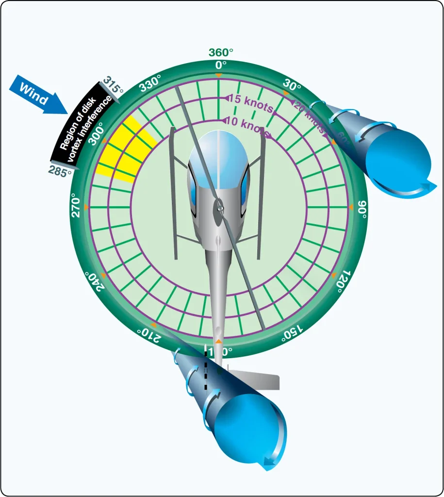
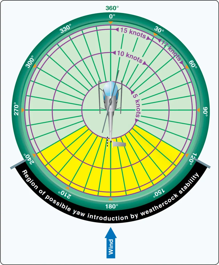
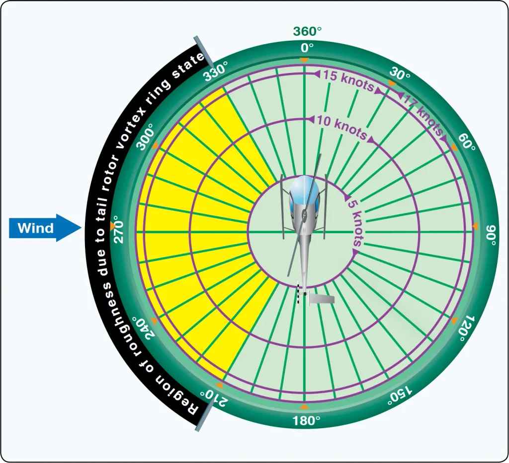
a. Worst case—relative wind within ±15° of the 10 o’clock position, generating vortices that can blow directly into the tail rotor. This is dictated by the characteristics of the helicopters aerodynamics of tailboom position, tail rotor size and position relative to the main rotor and vertical stabilizer, size and shape. [Figure 1]
Certain flight activities lend themselves to being at higher risk of LTE than others. For example, power line and pipeline patrol sectors, low speed aerial filming/photography as well as in the Police and Helicopter Emergency Medical Services (EMS) environments can find themselves in low-and-slow situations over geographical areas where the exact wind speed and direction are hard to determine.
Unfortunately, the aerodynamic conditions that a helicopter is susceptible to are not explainable in black and white terms. LTE is no exception. There are a number of contributing factors, but what is more important in preventing LTE is to note them, and then to associate them with situations that should be avoided. Whenever possible, pilots should learn to avoid the following combinations:
- Low and slow flight outside of ground effect.
- Winds from ±15º of the 10 o’clock position and probably on around to 5 o’clock position [Figure 1]
- Tailwinds that may alter the onset of translational lift and translational thrust, and hence induce high power demands and demand more anti-torque (left pedal) than the tail rotor can produce.
- Low speed downwind turns.
- Large changes of power at low airspeeds.
- Low speed flight in the proximity of physical obstructions that may alter a smooth airflow to both the main rotor and tail rotor.
Early detection of LTE, followed by the immediate flight control application of corrective action, applying forward cyclic to regain airspeed, applying right pedal not left as necessary to maintain rotor rpm, and reducing the collective (thus reducing the high-power demand on the tail rotor), is the key to a safe recovery. Pilots should always set themselves up when conducting any maneuver to have enough height and space available to recover in the event they encounter an aerodynamic situation such as LTE.
Understanding the aerodynamic phenomenon of LTE is by far the most important factor in preventing an LTE-related accident, and maintaining the ability and option either to go around if making an approach or pull out of a maneuver safely and re-plan, is always the safest option. Having the ability to fly away from a situation and re-think the possible options should always be part of a pilot’s planning process in all phases of flight. Unfortunately, there have been many pilots who have idled a good engine and fully functioning tail rotor disk and autorotated a perfectly airworthy helicopter to the crash site because they misunderstood or misperceived both the limitations of the helicopter and the aerodynamic situation.
Main Rotor Disk Interference (285–315°)
The effect of the main rotor disk vortex initially increases the AOA of the tail rotor blades, thus increasing tail rotor thrust. The increase in the AOA requires that right pedal pressure be added to reduce tail rotor thrust in order to maintain the same rate of turn. As the main rotor vortex passes the tail rotor, the tail rotor AOA is reduced. The reduction in the AOA causes a reduction in thrust and right yaw acceleration begins. This acceleration can be surprising, since previously adding right pedal to maintain the right turn rate. This thrust reduction occurs suddenly, and if uncorrected, develops into an uncontrollable rapid rotation about the mast. When operating within this region, be aware that the reduction in tail rotor thrust can happen quite suddenly, and be prepared to react quickly to counter this reduction with additional left pedal input.
Weathercock Stability (120–240°)
Tail Rotor Vortex Ring State (210–330°)
When the tail rotor thrust being generated is less than the thrust required, the helicopter yaws to the right. When hovering in left crosswinds, concentrate on smooth pedal coordination and do not allow an uncommanded right yaw to develop. If a right yaw rate is allowed to build, the helicopter can rotate into the wind azimuth region where weathercock stability then accelerates the right turn rate. Pilot workload during a tail rotor vortex ring state is high. Do not allow a right yaw rate to increase.
LTE at Altitude
Reducing the Onset of LTE
- Maintain maximum power-on rotor rpm. If the main rotor rpm is allowed to decrease, the antitorque thrust available is decreased proportionally.
- Avoid tailwinds below airspeeds of 30 knots. If loss of translational lift occurs, it results in an increased power demand and additional antitorque pressures.
- Avoid OGE operations and high-power demand situations below airspeeds of 30 knots at low altitudes.
- Be especially aware of wind direction and velocity when hovering in winds of about 8–12 knots. A loss of translational lift results in an unexpected high power demand and an increased antitorque requirement.
- Be aware that if a considerable amount of left pedal is being maintained, a sufficient amount of left pedal may not be available to counteract an unanticipated right yaw.
- Be alert to changing wind conditions, which may be experienced when flying along ridge lines and around buildings.
- Execute right turns slowly. This limits the effects of rotating inertia, and decreases loading on the tailrotor to control yawing.
Recovery Technique (Uncontrolled Right Yaw)
Collective pitch reduction aids in arresting the yaw rate but may cause an excessive rate of descent. Any large, rapid increase in collective to prevent ground or obstacle contact may further increase the yaw rate and decrease rotor rpm. The decision to reduce collective must be based on the pilot’s assessment of the altitude available for recovery.
If the rotation cannot be stopped and ground contact is imminent, an autorotation may be the best course of action. Maintain full left pedal until the rotation stops, then adjust to maintain heading. For more information on LTE, see Advisory Circular (AC) 90-95, Unanticipated Right Yaw in Helicopters.
Main Drive Shaft or Clutch Failure
Pilots should keep in mind that when there is any suspected mechanical malfunction, first and foremost they should always attempt to maintain rotor rpm. If the rotor rpm is at the normal indication with normal power settings, an instrument failure might be occurring, and it would be best to fly the helicopter to a safe landing area. If the rotor rpm is in fact decreasing or low, then there is a drive line failure.
Hydraulic Failure
An impending hydraulic failure can be recognized by a grinding or howling noise from the pump or actuators, increased control forces and feedback, and limited control movement. The required corrective action is stated in detail in the RFM. In most cases, airspeed needs to be reduced in order to reduce control forces. The hydraulic switch and circuit breaker should be checked and recycled. If hydraulic power is not restored, make a shallow approach to a running or roll-on landing. This technique is used because it requires less control force and pilot workload. Additionally, the hydraulic system should be disabled by placing the switch in the off position. The reason for this is to prevent an inadvertent restoration of hydraulic power, which may lead to overcontrolling near the ground.
In those helicopters in which the control forces are so high that they cannot be moved without hydraulic assistance, two or more independent hydraulic systems are installed. Some helicopters use hydraulic accumulators to store pressure that can be used for a short time while in an emergency if the hydraulic pump fails. This gives enough time to land the helicopter with normal control.
Governor or Fuel Control Failure
Abnormal Vibration
Low-Frequency Vibrations
Medium- and High-Frequency Vibrations
Most tail rotor vibrations fall into the high-frequency range (2,100 cycles per minute or higher) and can be felt through the tail rotor pedals as long as there are no hydraulic actuators to dampen out the vibration. This vibration is felt by the pilot through his or her feet, which are usually “put to sleep” by the vibration. The tail rotor operates at approximately a 6:1 ratio with the main rotor, meaning for every one rotation of the main rotor the tail rotor rotates 6 times. A main rotor operating rpm of 350 means the tail rotor rpm would be 2,100 rpm. Any imbalance in the tail rotor disk is very harmful as it can cause cracks to develop and rivets to work loose. Piston engines usually produce a normal amount of high-frequency vibration, which is aggravated by engine malfunctions, such as spark plug fouling, incorrect magneto timing, carburetor icing and/or incorrect fuel/air mixture. Vibrations in turbine engines are often difficult to detect as these engines operate at a very high rpm. Turbine engine vibration can be at 30,000 rpm internally, but common transmission speeds are in the 1,000 to 3,000 rpm range for the output shaft. The vibrations in turbine engines may be short lived as the engine disintegrates rapidly when damaged due to high rpm and the forces present.
Tracking and Balance
The use of a system such as a health and usage monitoring system (HUMS) provides the operator the ability to record engine and transmission performance and provide rotor track and balance. This system has been around for over 30 years and is now becoming more affordable, more capable, and more commonplace in the rotorcraft industry.