A typical alteration might consist of removing two pieces of radio equipment from the instrument panel and a power supply that was located in the baggage compartment behind the rear seat. In this example, these two pieces are replaced with a single lightweight, self-contained radio. At the same time, an old emergency locator transmitter (ELT) is removed from its mount near the tail, and a lighter weight unit is installed. A passenger seat is installed in the baggage compartment.
Computations Using Weight, Arm, and Moment
The first step in the weight and balance computation is to make a chart like the one in Figure 1, listing all of the items that are involved. The new center of gravity (CG) of 36.4 inches aft of the datum is determined by dividing the new moment by the new weight.
 |
| Figure 1. Weight, arm, and moment changes caused by typical alteration or repair |
Computations Using Weight and Moment Indexes
If the weight and balance data uses moment indexes rather than arms and moments, this same alteration can be computed using a chart such as the one in Figure 2. Subtract the weight and moment indexes of all the removed equipment from the empty weight and moment index of the airplane. Add the weight and moment indexes of all equipment installed to determine the total weight and the total moment index. To determine the position of the new CG in inches aft of the datum, multiply the total moment index by 100 to get the moment, and divide this by the total weight to get the new CG.
 |
| Figure 2. Weight and moment index changes caused by a typical alteration or repair |
Determining the CG in Percentage of Mean Aerodynamic Chord (Percent MAC)
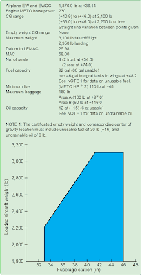
This procedure is the same as found in Chapter 5, Single-Engine Aircraft Weight and Balance Computations. Refer to the load conditions and CG information found in Figures 2, 3, and 4 to compute the CG in percent MAC:
 |
| Figure 3. Weight and balance information |
 |
| Figure 4. Loading conditions |
The loaded CG is +36.4 inches aft of the datum.
The MAC is 58.0 inches long.
The leading edge mean aerodynamic chord (LEMAC) is located at station 25.98.
The CG is +36.4 – 25.98 = 10.42 inches aft of LEMAC.
 |
| Figure 5. Formula for determining the CG in percent MAC |
