
RNAV encompasses a variety of underlying navigation systems and, therefore, approach criteria. This results in different sets of criteria for the final approach segment of various RNAV approaches. RNAV instrument approach criteria address the following procedures:
- GPS overlay of pre-existing nonprecision approaches.
- VOR/DME based RNAV approaches.
- Stand-alone RNAV (GPS) approaches.
- RNAV (GPS) approaches with vertical guidance (APV).
- RNAV (GPS) precision approaches (WAAS and LAAS).
GPS Overlay of Nonprecision Approach
The original GPS approach procedures provided authorization to fly non-precision approaches based on conventional, ground-based NAVAIDs. Many of these approaches have been converted to stand-alone approaches, and the few that remain are identified by the name of the procedure and “or GPS.”
These GPS non-precision approaches are predicated upon the design criteria of the ground-based NAVAID used as the basis of the approach. As such, they do not adhere to the RNAV design criteria for stand-alone GPS approaches, and are not considered part of the RNAV (GPS) approach classification for determining design criteria. [Figure 1]
 |
| Figure 1. Traditional GPS approach overlay |
GPS Stand-Alone/RNAV (GPS) Approach
 |
| Figure 2. Lincoln Muni KLNK Lincoln, Nebraska, RNAV GPS RWY 14 approach |
RNAV (GPS) Approach Using WAAS
WAAS was commissioned in July 2003, with IOC. Although precision approach capability is still in the future, WAAS currently provides a type of APV known as LPV. WAAS can support the following minima types: LPV, LNAV/VNAV, LP, and LNAV. Approach minima as low as 200 feet HAT and 1/2 SM visibility is possible, even though LPV is not considered a precision approach. WAAS covers 95 percent of the country 95 percent of the time.
Note: WAAS avionics receive an airworthiness approval in accordance with Technical Standard Order (TSO) C145, Airborne Navigation Sensors Using the Global Positioning System (GPS) Augmented by the Satellite Based Augmentation System (SBAS), or TSO-146, Stand-Alone Airborne Navigation Equipment Using the Global Positioning System (GPS) Augmented by the Satellite Based Augmentation System (SBAS), and installed in accordance with AC 20-138C, Airworthiness Approval of Positioning and Navigation Systems.
Precision approach capability will become available as more GBAS (LAAS) approach types become operational. GBAS (LAAS) further increases the accuracy of GPS and improves signal integrity warnings. Precision approach capability requires obstruction planes and approach lighting systems to meet Part 77 standards for ILS approaches. This delays the implementation of RNAV (GPS) precision approach capability due to the cost of certifying each runway.
ILS Approaches
Notwithstanding emerging RNAV technology, the ILS is the most precise and accurate approach NAVAID currently in use throughout the NAS. An ILS CAT I precision approach allows approaches to be made to 200 feet above the TDZE and with visibilities as low as 1,800 RVR; with CAT II and CAT III approaches allowing descents and visibility minimums that are even lower. Non-precision approach alternatives cannot begin to offer the precision or flexibility offered by an ILS. In order to further increase the approach capacity of busy airports and exploit the maximum potential of ILS technology, many different applications are in use.
An ILS system can accommodate up to 29 arrivals per hour on a single runway. Two or three parallel runways operating independently can double or triple the capacity of the airport. For air commerce, this means greater flexibility in scheduling passenger and cargo service. Capacity is increased through the use of simultaneous or converging ILS approaches, which are explained further in the corresponding paragraphs below.
In order to successfully accomplish simultaneous or converging ILS approaches, flight crews and ATC have additional responsibilities. When simultaneous instrument approaches are in use, ATC advises flight crews either directly or through ATIS of the active runways. It is the pilot’s responsibility to inform ATC if unable or unwilling to execute a simultaneous approach. Pilots must comply with all ATC requests in a timely manner and maintain strict radio discipline, including using complete aircraft call signs. It is also incumbent upon the flight crew to notify ATC immediately of any problems relating to aircraft communications or navigation systems. At the very least, the approach procedure briefing should cover the entire procedure including the approach name, runway number, frequencies, final approach course, glideslope intercept altitude, DA or DH, and the missed approach instructions. The review of autopilot procedures is also appropriate when making coupled ILS approaches.
As with all approaches, the primary navigation responsibility falls upon the pilot in command. ATC instructions will be limited to ensuring aircraft separation. Additionally, MAPs are designed to diverge in order to protect all involved aircraft. ILS approaches of all types are afforded the same obstacle clearance protection and design criteria, no matter how capacity is affected by simultaneous ILS approaches. [Figure 3]
 |
| Figure 3. ILS final approach segment design criteria |
ILS Approach Categories
There are three general classifications of ILS approaches: CAT I, CAT II, and CAT III (autoland). The basic ILS approach is a CAT I approach and requires only that pilots be instrument rated and current, and that the aircraft be equipped appropriately. CAT II and CAT III ILS approaches have lower minimums and require special certification for operators, pilots, aircraft, and airborne/ground equipment. Because of the complexity and high cost of the equipment, CAT III ILS approaches are used primarily in air carrier and military operations. [Figure 4]
 |
| Figure 4. ILS approach categories |
CAT II and III Approaches
The primary authorization and minimum RVRs allowed for an air carrier to conduct CAT II and III approaches can be found in OpSpecs Part C. CAT II and III operations allow authorized pilots to make instrument approaches in weather that would otherwise be prohibitive.
While CAT I ILS operations permit substitution of midfield RVR for TDZ RVR (when TDZ RVR is not available), CAT II ILS operations do not permit any substitutions for TDZ RVR. The TDZ RVR system is required and must be used. The TDZ RVR is controlling for all CAT II ILS operations.
The weather conditions encountered in CAT III operations range from an area where visual references are adequate for manual rollout in CAT IIIa, to an area where visual references are inadequate even for taxi operations in CAT IIIc. To date, no U.S. operator has received approval for CAT IIIc in OpSpecs. Depending on the auto-flight systems, some aircraft require a DH to ensure that the aircraft is going to land in the TDZ and some require an Alert Height as a final cross-check of the performance of the auto-flight systems. These heights are based on radio altitude (RA) and can be found in the specific aircraft’s AFM. [Figure 5]
 |
| Figure 5. Category III approach procedure |
Simultaneous Approaches To Parallel Runways
Airports that have two or more parallel runways may be authorized to use simultaneous parallel approaches to maximize the capacity of the airport. Depending on the runway centerline separation and ATC procedures, there are three classifications of simultaneous parallel approaches: Simultaneous dependent approaches, simultaneous independent approaches and simultaneous independent close parallel approaches. A simultaneous dependent approach differs from a simultaneous independent approach in that the minimum distance between parallel runway centerlines may be less. A staggered separation of aircraft on the adjacent final approach course is required; but there is no requirement for a No Transgression Zone (NTZ) or Final Monitor Controllers. An independent approach eliminates the need for staggered approaches and aircraft may be side by side or pass if speeds are different.
NOTE:
- Simultaneous approaches involving an RNAV approach may only be conducted when (GPS) appears in the approach title or a chart note states that GPS is required. See the “ILS Approaches” paragraph above for information about pilot responsibilities when simultaneous approaches are in use.
- Flight Director or Autopilot requirements for simultaneous operations will be annotated on the approach chart.
- Simultaneous approaches may only be conducted where instrument approach charts specifically authorize simultaneous approaches.
Simultaneous Dependent Approaches
 |
| Figure 6. Classification of Simultaneous Parallel Approaches |
 |
| Figure 7. Sacramento International KSMF, Sacramento, California, ILS or LOC RWY 16L |
Simultaneous Independent Approaches
Dual and triple simultaneous independent parallel instrument approaches, are authorized at certain airports with specified distances between parallel runway centerlines. As a part of the simultaneous independent approach approval, an NTZ must be established to ensure proper flight track boundaries for all aircraft. Outside of the NTZ, normal operating zones (NOZ) indicate the operating zone within which aircraft remain during normal approach operations. The NOZ between the final approach courses varies in width depending on the runway centerline spacing. The NTZ is defined as a 2,000-foot wide area located equidistant between the final approach courses in which flight is not allowed during the simultaneous operation. [Figure 8] Any time an aircraft breaches or is anticipated to breach the NTZ, ATC issues instructions for the threatened aircraft on the adjacent final approach course to break off the approach to avoid potential conflict.
 |
| Figure 8. Simultaneous Independent Approach Example Using ILS Approaches |
 |
| Figure 9. Charlotte Douglas International KCLT, Charlotte, North Carolina, ILS or LOC RWY 18L |
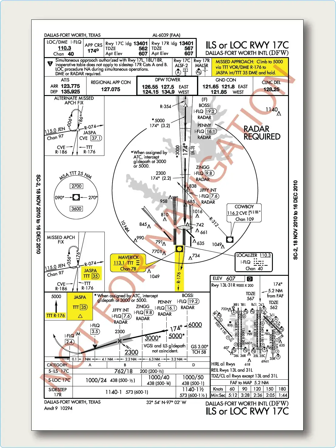 |
| Figure 10 Missed approach procedures for Dallas-Fort Worth International (DFW)4 |
Simultaneous Close Parallel Precision Runway Monitor (PRM) Approaches
Simultaneous close parallel (independent) PRM approaches are authorized for use at designated airports that have parallel runways spaced less than 4,300 feet apart. [Figure 11]
 |
| Figure 11. Simultaneous independent close parallel approach example using ILS PRM approaches |
 |
| Figure 12. Example of Simultaneous close parallel instrument approach: Atlanta, Georgia, ILS PRM RWY 10 and AAUP |
- Immediately follow break out instructions as soon as safety permits.
- Use of the AAUP.
- Use of dual VHF communications.
- Completion of required PRM training.
- Hand flying any breakout instruction. It is important to note that descending breakouts, though rare, may be issued. Flight crews will never be issued breakout instructions that clear them to an altitude below the MVA, and they are not required to descend at more than 1,000 fpm.
- Traffic Alert and Collision Avoidance System (TCAS) is not required to conduct a PRM approach. For aircraft so equipped, if the controller’s climb/descend instruction differs from the TCAS resolution advisory (RA), pilots must follow the RA while continuing to follow the controller’s turn instruction. Report this deviation to ATC as soon as practical.
Simultaneous Offset Instrument Approaches (SOIAs)
SOIAs allow simultaneous approaches to two parallel runways spaced at least 750 feet apart, but less than 3,000 feet. Traditionally, the SOIA procedure has used an ILS/ PRM approach to one runway and an offset localizer-type directional aid (LDA)/PRM approach with glideslope to the adjacent runway. Now, RNAV (GPS) and RNAV (RNP) approaches may also be used for SOIA.” Approach charts will include procedural notes, such as “Simultaneous Close Parallel approach authorized with LDA PRM RWY 28R and RNAV (GPS) PRM X RWY 28R.” or “Simultaneous approach authorized”. San Francisco had the first published SOIA approach. [Figure 13]
 |
| Figure 13. Example of Approach and AAUP used for Simultaneous Offset Instrument Approach Procedure |
Converging ILS Approaches
Another method by which ILS approach capacity can be increased is through the use of converging approaches. Converging approaches may be established at airports that have runways with an angle between 15° and 100° and each runway must have an ILS. Additionally, separate procedures must be established for each approach, and each approach must have a MAP at least 3 NM apart with no overlapping of the protected missed approach airspace. Only straight-in approaches are approved for converging ILS procedures. If the runways intersect, the controller must be able to visually separate intersecting runway traffic.
Approaches to intersecting runways generally have higher minimums, commonly with 600-foot ceiling and 1 1/4 to 2 mile visibility requirements. Pilots are informed of the use of converging ILS approaches by the controller upon initial contact or through ATIS. [Figure 14]
 |
| Figure 14. Converging approach criteria |
 |
| Figure 15. Dallas-Fort Worth KDFW, Dallas-Fort Worth, Texas, CONVERGING ILS RWY 35C |
VOR Approach
The VOR is one of the most widely used non-precision approach types in the NAS. VOR approaches use VOR facilities both on and off the airport to establish approaches and include the use of a wide variety of equipment, such as DME and TACAN. Due to the wide variety of options included in a VOR approach, TERPS outlines design criteria for both on and off airport VOR facilities, as well as VOR approaches with and without a FAF. Despite the various configurations, all VOR approaches are non-precision approaches, require the presence of properly operating VOR equipment, and can provide MDAs as low as 250 feet above the runway. VOR also offers a flexible advantage in that an approach can be made toward or away from the navigational facility.
The VOR approach into Fort Rucker, Alabama, is an example of a VOR approach where the VOR facility is on the airport and there is no specified FAF. [Figure 16] For a straight-in approach, the final approach course is typically aligned to intersect the extended runway centerline 3,000 feet from the runway threshold, and the angle of convergence between the two does not exceed 30°. This type of VOR approach also includes a minimum of 300 feet of obstacle clearance in the final approach area. The final approach area criteria include a 2 NM wide primary area at the facility that expands to 6 NM wide at a distance of 10 NM from the facility. Additional approach criteria are established for courses that require a high altitude teardrop approach penetration.
 |
| Figure 16. Fort Rucker, Alabama, KOZR VOR RWY 6 |
, Alexandria, Louisiana, KAEX VOR DME RWY 32") |
| Figure 17. Alexandria International (AEX), Alexandria, Louisiana, KAEX VOR DME RWY 32 |
NDB Approach
Like the VOR approach, an NDB approach can be designed using facilities both on and off the airport, with or without a FAF, and with or without DME availability. At one time, it was commonplace for an instrument student to learn how to fly an NDB approach, but with the growing use of GPS, many pilots no longer use the NDB for instrument approaches. New RNAV approaches are also rapidly being constructed into airports that are served only by NDB. The long-term plan includes the gradual phase out of NDB facilities, and eventually, the NDB approach becomes nonexistent. Until that time, the NDB provides additional availability for instrument pilots into many smaller, remotely located airports.
The NDB Runway 35 approach at Carthage/Panola County Sharpe Field is an example of an NDB approach established with an on-airport NDB that does not incorporate a FAF. [Figure 18] In this case, a procedure turn or penetration turn is required to be a part of the approach design. For the NDB to be considered an on-airport facility, the facility must be located within one mile of any portion of the landing runway for straight-in approaches and within one mile of any portion of usable landing surface for circling approaches. The final approach segment of the approach is designed with a final approach area that is 2.5 NM wide at the facility and increases to 8 NM wide at 10 NM from the facility. Additionally, the final approach course and the extended runway centerline angle of convergence cannot exceed 30° for straight-in approaches. This type of NDB approach is afforded a minimum of 350 feet obstacle clearance.
, NDB RWY 35") |
| Figure 18. Carthage/Panola County-Sharpe Field, Carthage, Texas, (K4F2), NDB RWY 35 |
, NDB/DME or GPS RWY 6R") |
| Figure 19. Tucson/Ryan Field, Tuscson, Arizona, (KRYN), NDB/DME or GPS RWY 6R |
Radar Approaches
The two types of radar approaches available to pilots when operating in the NAS are precision approach radar (PAR) and airport surveillance radar (ASR). Radar approaches may be given to any aircraft at the pilot’s request. ATC may also offer radar approach options to aircraft in distress regardless of the weather conditions or as necessary to expedite traffic. Despite the control exercised by ATC in a radar approach environment, it remains the pilot’s responsibility to ensure the approach and landing minimums listed for the approach are appropriate for the existing weather conditions considering personal approach criteria certification and company OpSpecs.
Perhaps the greatest benefit of either type of radar approach is the ability to use radar to execute a no gyro approach. Assuming standard rate turns, ATC can indicate when to begin and end turns. If available, pilots should make use of this approach when the heading indicator has failed and partial panel instrument flying is required.
Information about radar approaches is published in tabular form in the front of the TPP booklet. PAR, ASR, and circling approach information including runway, DA, DH, or MDA, height above airport (HAA), HAT, ceiling, and visibility criteria are outlined and listed by specific airport.
Regardless of the type of radar approach in use, ATC monitors aircraft position and issues specific heading and altitude information throughout the entire approach. Particularly, lost communications procedures should be briefed prior to execution to ensure pilots have a comprehensive understanding of ATC expectations if radio communication were lost. ATC also provides additional information concerning weather and missed approach instructions when beginning a radar approach. [Figure 20]
 |
| Figure 20. Asheville Regional KAVL, Asheville, North Carolina, radar instrument approach minimums |
Precision Approach Radar (PAR)
PAR provides both vertical and lateral guidance, as well as range, much like an ILS, making it the most precise radar approach available. The radar approach, however, is not able to provide visual approach indications in the flight deck. This requires the flight crew to listen and comply with controller instructions. PAR approaches are rare, with most of the approaches used in a military setting; any opportunity to practice this type of approach is beneficial to any flight crew. The final approach course of a PAR approach is normally aligned with the runway centerline, and the associated glideslope is typically no less than 2.5° and no more than 3°. Obstacle clearance for the final approach area is based on the particular established glideslope angle and the exact formula is outlined in FAA Order 8260.3. [Figure 21]
 |
| Figure 21. PAR final approach area criteria |
Airport Surveillance Radar (ASR)
ASR approaches are typically only approved when necessitated for an ATC operational requirement or in an unusual or emergency situation. This type of radar only provides heading and range information, although the controller can advise the pilot of the altitude where the aircraft should be based on the distance from the runway. An ASR approach procedure can be established at any radar facility that has an antenna within 20 NM of the airport and meets the equipment requirements outlined in FAA Order 8200.1, U.S. Standard Flight Inspection Manual. ASR approaches are not authorized for use when Center Radar ARTS processing (CENRAP) procedures are in use due to diminished radar capability. The final approach course for an ASR approach is aligned with the runway centerline for straight-in approaches and aligned with the center of the airport for circling approaches. Within the final approach area, the pilot is also guaranteed a minimum of 250 feet obstacle clearance. ASR descent gradients are designed to be relatively flat, with an optimal gradient of 150 feet per mile and never exceeding 300 feet per mile.
Localizer Approaches
As an approach system, the localizer is an extremely flexible approach aid that, due to its inherent design, provides many applications for a variety of needs in instrument flying. An ILS glideslope installation may be impossible due to surrounding terrain. The localizer is able to provide four separate types of non-precision approaches from one approach system:
- Localizer approach
- Localizer/DME approach
- Localizer back course approach
- Localizer-type directional aid (LDA)
Localizer and Localizer DME
The localizer approach system can provide both precision and non-precision approach capabilities to a pilot. As a part of the ILS system, the localizer provides horizontal guidance for a precision approach. Typically, when the localizer is discussed, it is thought of as a non-precision approach due to the fact that either it is the only approach system installed, or the glideslope is out of service on the ILS. In either case, the localizer provides a non-precision approach using a localizer transmitter installed at a specific airport. [Figure 22]
 |
| Figure 22. Vicksburg Tallulah Regional KTVR, Tallulah Vicksburg, Louisiana, LOC RWY 36 |
 |
| Figure 23. Vicksburg Tallulah Regional KTVR, Tallulah Vicksburg, Louisiana, LOC RWY 36 |
Localizer Back Course
In cases where an ILS is installed, a back course may be available in conjunction with the localizer. Like the localizer, the back course does not offer a glideslope, but remember that the back course can project a false glideslope signal and the glideslope should be ignored. Reverse sensing occurs on the back course using standard VOR equipment.
With a horizontal situation indicator (HSI) system, reverse sensing is eliminated if it is set appropriately to the front course. [Figure 24]
 |
| Figure 24. Dayton Beach International DAB, Dayton Beach, Florida, LOC BC RWY 25R |
Localizer-Type Directional Aid (LDA)
The LDA is of comparable use and accuracy to a localizer but is not part of a complete ILS. The LDA course usually provides a more precise approach course than the similar simplified directional facility (SDF) installation, which may have a course width of 6° or 12°.
The LDA is not aligned with the runway. Straight-in minimums may be published where alignment does not exceed 30° between the course and runway. Circling minimums only are published where this alignment exceeds 30°.
A very limited number of LDA approaches also incorporate a glideslope. These are annotated in the plan view of the instrument approach chart with a note, “LDA/Glideslope.” These procedures fall under a newly defined category of approaches called Approach (Procedure) with Vertical Guidance (aviation) APVs. LDA minima for with and without glideslope is provided and annotated on the minima lines of the approach chart as S−LDA/GS and S−LDA. Because the final approach course is not aligned with the runway centerline, additional maneuvering is required compared to an ILS approach. [Figure 25]
 |
| Figure 25. Hartford Brainard KHFD, Hartford, Connecticut, LDA RWY 2 |
Simplified Directional Facility (SDF)
The SDF provides a final approach course similar to that of the ILS localizer. It does not provide glideslope information. A clear understanding of the ILS localizer and the additional factors listed below completely describe the operational characteristics and use of the SDF. [Figure 26]
 |
| Figure 26. Lebanon Floyd W Jones, Lebanon, Missouri, SDF RWY 36 |