As mentioned before, STARs include navigation fixes that are used to provide transition and arrival routes from the en route structure to the final approach course. They also may lead to a fix where radar vectors are provided to intercept the final approach course. Pilots may have noticed that minimum crossing altitudes and airspeed restrictions appear on some STARs. These expected altitudes and airspeeds are not part of the clearance until ATC includes them verbally. A STAR is simply a published routing; it does not have the force of a clearance until issued specifically by ATC. For example, minimum en route altitude (MEAs) printed on STARs are not valid unless stated within an ATC clearance or in cases of lost communication. After receiving the arrival clearance, the aircrew should review the assigned STAR procedure and ensure the FMS has the appropriate procedure loaded (if so equipped). Obtain the airport and weather information as early as practical. It is recommended that pilots have this information prior to flying the STAR. If you are landing at an airport with approach control services that has two or more published instrument approach procedures, you will receive advance notice of which instrument approaches to expect. This information is broadcast either by ATIS or by a controller. [Figure 1] It may not be provided when the visibility is 3 SM or better and the ceiling is at or above the highest initial approach altitude established for any instrument approach procedure for the airport.
 |
| Figure 1. Arrival clearance |
For STAR procedures charted with radar vectors to the final approach, look for routes from the STAR terminating fixes to the IAF. If no route is depicted, you should have a predetermined plan of action to fly from the STAR terminating fix to the IAF in the event of a communication failure.
Reviewing the Approach
Once the aircrew has determined which approach to expect, review the approach chart thoroughly before entering the terminal area. Aircrews should check fuel level and make sure a prolonged hold or increased headwinds have not cut into the aircraft’s fuel reserves because there is always a chance the pilot has to make a missed approach or go to an alternate. By completing landing checklists early, aircrews can concentrate on the approach.
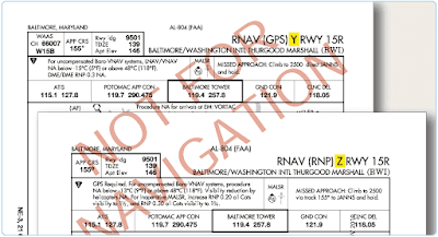
In setting up for the expected approach procedure when using an RNAV, GPS, or FMS system, it is important to understand how multiple approaches to the same runway are coded in the database. When more than one RNAV procedure is issued for the same runway, there must be a way to differentiate between them within the equipment’s database, as well as to select which procedure is to be used. (Multiple procedures may exist to accommodate GPS receivers and FMS, both with and without VNAV capability.) Each procedure name incorporates a letter of the alphabet, starting with Z and working backward through Y, X, W, and so on. (Naming conventions for approaches are covered in more depth in the Apporoches section). [Figure 2]
Altitude
Upon arrival in the terminal area, ATC either clears the aircraft to a specific altitude, or they give it a “descend via” clearance that instructs the pilot to follow the altitudes published on the STAR. [Figure 3] Pilots are not authorized to leave their last assigned altitude unless specifically cleared to do so. If ATC amends the altitude or route to one that is different from the published procedure, the rest of the charted descent procedure is canceled. ATC assigns any further route, altitude, or airspeed clearances, as necessary. Notice the JANESVILLE FOUR ARRIVAL depicts only one published arrival route, with no named transition routes leading to the basic STAR procedure beginning at the Janesville VOR/DME. VNAV planning information is included for turbojet and turboprop aircraft at the bottom of the chart. Additionally, note that there are several ways to identify the BRIBE reporting point using alternate formation radials, some of which are from off- chart NAVAIDs. ATC may issue a descent clearance that includes a crossing altitude restriction. In the PENNS ONE ARRIVAL, the ATC clearance authorizes aircraft to descend at the pilots’ discretion, as long as the pilot crosses the PENNS Intersection at 6,000 feet MSL. [Figure 4]
 |
| Figure 3. Assigned altitudes |
 |
| Figure 4. Altitude restrictions |
In the United States, Canada, and many other countries, the common altitude for changing to the standard altimeter setting of 29.92 inches of mercury (“Hg) (or 1013.2 hectopascals or millibars) when climbing to the high altitude structure is 18,000 feet. When descending from high altitude, the altimeter should be changed to the local altimeter setting when passing through FL 180, although in most countries throughout the world the change to or from the standard altimeter setting is not done at the same altitude for each instance.
For example, the flight level where aircrews change their altimeter setting to the local altimeter setting is specified by ATC each time they arrive at a specific airport. This information is shown on STAR charts outside the United States with the words: TRANS LEVEL: BY ATC. When departing from that same airport (also depicted typically on the STAR chart), the altimeter should be set to the standard setting when passing through 5,000 feet, as an example. This means that altimeter readings when flying above 5,000 feet are actual flight levels, not feet. This is common for Europe, but very different for pilots experienced with flying in the United States and Canada.
Although standardization of these procedures for terminal locations is subject to local considerations, specific criteria apply in developing new or revised arrival procedures. Normally, high performance aircraft enter the terminal area at or above 10,000 feet above the airport elevation and begin their descent 30 to 40 NM from touchdown on the landing runway. Unless pilots indicate an operational need for a lower altitude, descent below 5,000 feet above the airport elevation is typically limited to an altitude where final descent and glideslope/glidepath intercept can be made without exceeding specific obstacle clearance and other related arrival, approach, and landing criteria. Arrival delays typically are absorbed at a metering fix. This fix is established on a route prior to the terminal airspace, 10,000 feet or more above the airport elevation. The metering fix facilitates profile descents, rather than controllers using delaying vectors or a holding pattern at low altitudes. Descent restrictions normally are applied prior to reaching the final approach phase to preclude relatively high descent rates close in to the destination airport. At least 10 NM from initial descent from 10,000 feet above the airport elevation, the controller issues an advisory that details when to expect to commence the descent. ATC typically uses the phraseology, “Expect descent in (number) miles.” Standard ATC phraseology is, “Maintain (altitude) until specified point (e.g., abeam landing runway end), cleared for visual approach or expect visual or contact approach clearance in (number of miles, minutes, or specified point).”
Remember during arrivals, when cleared for an instrument approach, maintain the last assigned altitude until established on a published segment of the approach or on a segment of a published route. If no altitude is assigned with the approach clearance and the aircraft is already on a published segment, the pilot can descend to its minimum altitude for that segment of the approach.
Airspeed
During the arrival, expect to make adjustments in speed at the controller’s request. When pilots fly a high-performance aircraft on an IFR flight plan, ATC may ask them to adjust their airspeed to achieve proper traffic sequencing and separation. This also reduces the amount of radar vectoring required in the terminal area. When operating a reciprocating engine or turboprop airplane within 20 NM from the destination airport, 150 knots is usually the slowest airspeed that is assigned. If the aircraft cannot maintain the assigned airspeed, the pilot must advise ATC. Controllers may ask pilots to maintain the same speed as the aircraft ahead of or behind them on the approach. Pilots are expected to maintain the specified airspeed ±10 knots. At other times, ATC may ask pilots to increase or decrease airspeed by 10 knots, or multiples thereof. When the speed adjustment is no longer needed, ATC advises the pilot to “… resume normal speed.”
Keep in mind that the maximum speeds specified in 14 CFR Part 91, § 91.117 still apply during speed adjustments. It is the pilot’s responsibility to advise ATC if an assigned speed adjustment would cause an exceedence of these limits. For operations in Class C or D airspace at or below 2,500 feet above ground level (AGL), within 4 NM of the primary airport, ATC has the authority to approve a faster speed than those prescribed in 14 CFR Part 91, § 91.117.
Pilots operating at or above 10,000 feet MSL on an assigned speed adjustment that is greater than 250 KIAS are expected to reduce speed to 250 KIAS to comply with 14 CFR Part 91, § 91.117(a) when cleared below 10,000 feet MSL, within domestic airspace. This speed adjustment is made without notifying ATC. Pilots are expected to comply with the other provisions of 14 CFR Part 91, § 91.117 without notifying ATC. For example, it is normal for faster aircraft to level off at 10,000 feet MSL while slowing to the 250 KIAS limit that applies below that altitude, and to level off at 2,500 feet above airport elevation to slow to the 200 KIAS limit that applies within the surface limits of Class C or D airspace. Controllers anticipate this action and plan accordingly.
Speed restrictions of 250 knots do not apply to aircraft operating beyond 12 NM from the coastline within the United States Flight Information Region in offshore Class E airspace below 10,000 feet MSL. In airspace underlying a Class B airspace area designated for an airport, pilots are expected to comply with the 200 KIAS limit specified in 14 CFR Part 91, § 91.117(c). (See 14 CFR Part 91, § 91.117(c) and 91.703.) Approach clearances cancel any previously assigned speed adjustment.
Holding Patterns
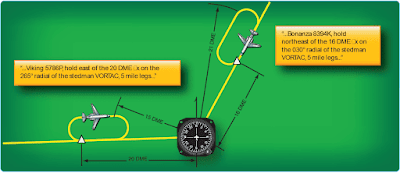
If aircraft reach a clearance limit before receiving a further clearance from ATC, a holding pattern is required at the last assigned altitude. Controllers assign holds for a variety of reasons, including deteriorating weather or high traffic volume. Holding might also be required following a missed approach. Since flying outside the area set aside for a holding pattern could lead to an encounter with terrain or other aircraft, aircrews need to understand the size of the protected airspace that a holding pattern provides. Each holding pattern has a fix, a direction to hold from the fix, and an airway, bearing, course, radial, or route on which the aircraft is to hold. These elements, along with the direction of the turns, define the holding pattern.
Since the speed of the aircraft affects the size of a holding pattern, maximum holding airspeeds have been designated to limit the amount of airspace that must be protected. The three airspeed limits are shown in Figure 5. Some holding patterns have additional airspeed restrictions to keep faster aircraft from flying out of the protected area. These are depicted on charts by using an icon and the limiting airspeed.
 |
| Figure 5. Maximum holding speeds for different altitudes |
DME and IFR-certified GPS equipment offer some additional options for holding. Rather than being based on time, the leg lengths for DME/GPS holding patterns are based on distances in nautical miles. These patterns use the same entry and holding procedures as conventional holding patterns. The controller or the instrument approach procedure chart specifies the length of the outbound leg. The end of the outbound leg is determined by the DME or the along track distance (ATD) readout. The holding fix on conventional procedures, or controller-defined holding based on a conventional navigation aid with DME, is a specified course or radial and distances are from the DME station for both the inbound and outbound ends of the holding pattern. When flying published GPS overlay or standalone procedures with distance specified, the holding fix is a waypoint in the database and the end of the outbound leg is determined by the ATD. Instead of using the end of the outbound leg, some FMS are programmed to cue the inbound turn so that the inbound leg length matches the charted outbound leg length.
Normally, the difference is negligible, but in high winds, this can enlarge the size of the holding pattern. Aircrews need to understand their aircraft’s FMS holding program to ensure that the holding entry procedures and leg lengths match the holding pattern. Some situations may require pilot intervention in order to stay within protected airspace. [Figure 6]
Approach Clearance
The approach clearance provides guidance to a position from where the pilot can execute the approach. It is also a clearance to fly that approach. If only one approach procedure exists, or if ATC authorizes the aircrew to execute the approach procedure of their choice, the clearance may be worded as simply as “… cleared for approach.” If ATC wants to restrict the pilot to a specific approach, the controller names the approach in the clearance. For example, “…cleared ILS Runway 35 Right approach.”
When the landing is to be made on a runway that is not aligned with the approach being flown, the controller may issue a circling approach clearance, such as “…cleared for VOR Runway 17 approach, circle to land Runway 23.” Approaches whose final approach segment is more than 30 degrees different from the landing runway alignment are always designated as circling approaches. Unless a specific landing runway is specified in the approach clearance, the pilot may land on any runway. Pilots landing at non-towered airports are reminded of the importance of making radio calls as set forth in the AIM.
When cleared for an approach prior to reaching a holding fix, ATC expects the pilot to continue to the holding fix, along the feeder route associated with the fix, and then to the IAF. If a feeder route to an IAF begins at a fix located along the route of flight prior to reaching the holding fix, and clearance for an approach is issued, the pilot should commence the approach via the published feeder route. The pilot is expected to commence the approach in a similar manner at the IAF, if the IAF is located along the route to the holding fix.
ATC also may clear an aircraft directly to the IAF by using language such as “direct” or “proceed direct.” Controllers normally identify an approach by its published name, even if some component of the approach aid (such as the glideslope of an ILS) is inoperative or unreliable. The controller uses the name of the approach as published but advises the aircraft when issuing the approach clearance that the component is unusable.
Present Position Direct
In addition to using high and low altitude en route charts as resources for arrivals, area charts can be helpful as a planning aid for SA. Many pilots find the area chart helpful in locating a depicted fix after ATC clears them to proceed to a fix and hold, especially at unfamiliar airports.
Looking at Figures 7 and 8 assume the pilot is on V295 northbound en route to Palm Beach International Airport. The pilot is en route on the airway when the controller clears him present position direct to the ZISUR (IAF) and for the ILS approach. There is no transition authorized or charted between his present position and the approach facility. There is no minimum altitude published for the route the pilot is about to travel.
 |
| Figure 7. Cleared present position direct from V295 |
 |
| Figure 8. Cleared for the Palm Beach ILS approach |
In Figure 8, the pilot is just north of HEATT Intersection at 5,000 feet when the approach controller states, “Citation 9724J, two miles from HEATT, cleared present position direct ZISUR, cleared for the Palm Beach ILS Runway 10L Approach, contact Palm Beach Tower on 119.1 established inbound.”With no minimum altitude published from that point to the ZISUR intersection, the pilot should maintain the last assigned altitude until he reaches the IAF. In Figure 7, after passing ZISUR intersection outbound, commence the descent to 2,000 feet for the course reversal. The ILS procedure relies heavily on the controller’s recognition of the restriction upon the pilot to maintain the last assigned altitude until “established” on a published segment of the approach. Prior to issuing a clearance for the approach, the controller usually assigns the pilot an altitude to maintain until established on the final approach course , compatible with glideslope intercept.
Radar Vectors to Final Approach Course
Arriving aircraft usually are vectored to intercept the final approach course, except with vectors for a visual approach, at least 2 NM outside the approach gate unless one of the following exists:
- When the reported ceiling is at least 500 feet above the minimum vectoring altitude or minimum IFR altitude and the visibility is at least 3 NM (report may be a pilot report if no weather is reported for the airport), aircraft may be vectored to intercept the final approach course closer than 2 NM outside the approach gate but no closer than the approach gate.
- If specifically requested by a pilot, ATC may vector aircraft to intercept the final approach course inside the approach gate but no closer than the final approach fix (FAF).
For a precision approach, aircraft are vectored at an altitude that is not above the glideslope/glidepath or below the minimum glideslope/glidepath intercept altitude specified on the approach procedure chart. For a non-precision approach, aircraft are vectored at an altitude that allows descent in accordance with the published procedure.
When a vector takes the aircraft across the final approach course, pilots are informed by ATC and the reason for the action is stated. In the event that ATC is not able to inform the aircraft, the pilot is not expected to turn inbound on the final approach course unless an approach clearance has been issued. An example of ATC phraseology in this case is, “… expect vectors across final for spacing.”
The following ATC arrival instructions are issued to an IFR aircraft before it reaches the approach gate:
- Position relative to a fix on the final approach course. If none is portrayed on the controller’s radar display or if none is prescribed in the instrument approach procedure, ATC issues position information relative to the airport or relative to the NAVAID that provides final approach guidance.
- Vector to intercept the final approach course if required.
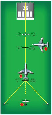
- Approach clearance except when conducting a radar approach. ATC issues the approach clearance only after the aircraft is established on a segment of a published route or instrument approach procedure, or in the following examples as depicted in Figure 9.
 |
| Figure 9. Arrival instructions when established |
Aircraft 1 was vectored to the final approach course but clearance was withheld. It is now at 4,000 feet and established on a segment of the instrument approach procedure. “Seven miles from X-RAY. Cleared ILS runway three six approach.”
Aircraft 2 is being vectored to a published segment of the final approach course, 4 NM from LIMA at 2,000 feet. The minimum vectoring altitude for this area is 2,000 feet. “Four miles from LIMA. Turn right heading three four zero. Maintain two thousand until established on the localizer. Cleared ILS runway three six approach.”
Aircraft 3: There are many times when it is desirable to position an aircraft onto the final approach course prior to a published, charted segment of an instrument approach procedure (IAP).
Sometimes IAPs have no initial segment and require vectors. “RADAR REQUIRED” is charted in the plan view. Sometimes a route intersects an extended final approach course making a long intercept desirable.
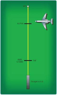
If an aircraft is not established on a segment of a published approach and is not conducting a radar approach, ATC assigns an altitude to maintain until the aircraft is established on a segment of a published route or instrument approach procedure. [Figure 10]
 |
| Figure 10. Arrival instructions when not established |
The aircraft is being vectored to a published segment of the ILS final approach course, 3 NM from Alpha at 4,000 feet. The minimum vectoring altitude for this area is 4,000 feet. “Three miles from Alpha. Turn left heading two one zero. Maintain four thousand until established on the localizer Cleared ILS runway one eight approach.”
The ATC assigned altitude ensures IFR obstruction clearance from the point at which the approach clearance is issued until established on a segment of a published route or instrument approach procedure.
ATC tries to make frequency changes prior to passing the FAF, although when radar is used to establish the FAF, ATC informs the pilot to contact the tower on the local control frequency after being advised that the aircraft is over the fix. For example, “Three miles from final approach fix. Turn left heading zero one zero. Maintain two thousand until established on the localizer. Cleared ILS runway three six approach. I will advise when over the fix.”


