
The visual preflight assessment mitigates airplane flight hazards. The preflight assessment ensures that any aircraft flown meets regulatory airworthiness standards and is in a safe mechanical condition prior to flight. Per 14 CFR part 3, section 3.5(a), the term “airworthy” means that the aircraft conforms to its type design and is in condition for safe operation. The owner/operator is primarily responsible for maintenance, but in accordance with 14 CFR part 91, section 91.7(a) and (b) no person may operate a civil aircraft unless it is in an airworthy condition and the pilot in command of a civil aircraft is responsible for determining whether the aircraft is in condition for safe flight. The pilot’s inspection should involve the following:
- Inspecting the airplane’s airworthiness status.
- Following the AFM/POH to determine the required items for visual inspection. [Figures 1, 2, 3].


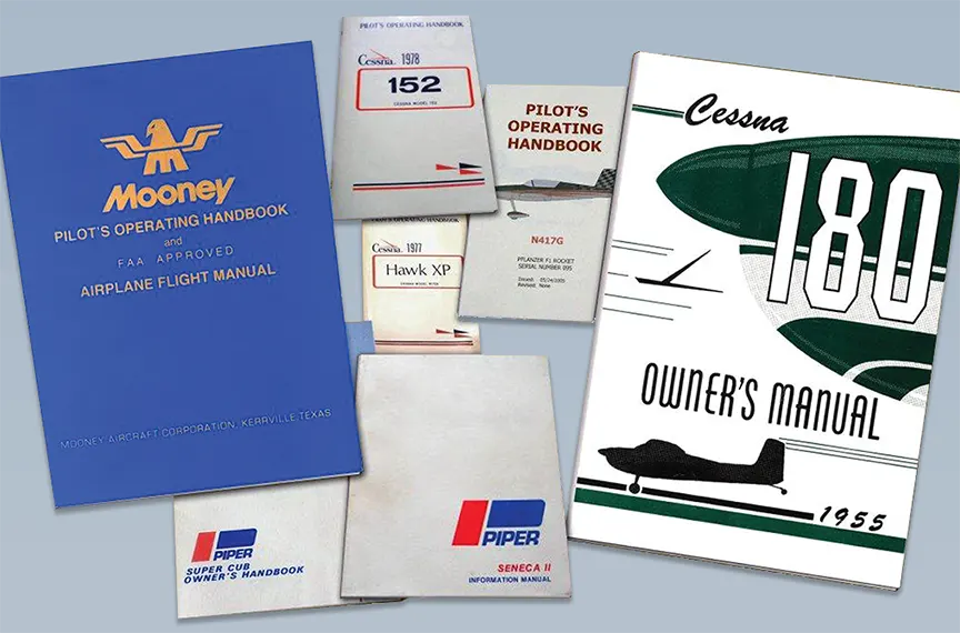
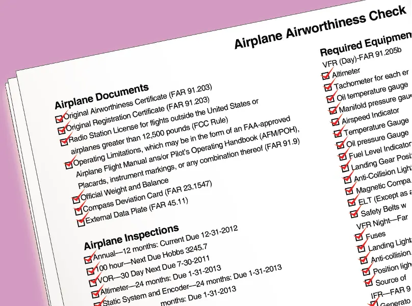
Each airplane has a set of logbooks that include airframe and engine, and in some cases, propeller and appliance logbooks, which are used to record maintenance, alteration, and inspections performed on a specific airframe, engine, propeller, or appliance. It is important that the logbooks be kept accurate, secure, and available for inspection. Airplane logbooks are not normally kept in the airplane. It should be a matter of procedure by the pilot to inspect the airplane logbooks or a summary of the airworthy status prior to flight to ensure that the airplane records of maintenance, alteration, and inspections are current and correct. [Figure 4] The following is required:
- Annual inspection within the preceding 12 calendar months (Title 14 of the Code of Federal Regulations (14 CFR) part 91, section 91.409(a))
- 100-hour inspection, if the aircraft is operated for hire (14 CFR part 91, section 91.409(b))
- Transponder certification within the preceding 24 calendar months (14 CFR part 91, section 91.413)
- Static system and encoder certification, within the preceding 24 calendar months, required for instrument flight rules (IFR) flight in controlled airspace (14 CFR part 91, section 91.411)
- 30-day VHF omnidirectional range (VOR) equipment check when using the VOR system of radio navigation for IFR flight (14 CFR part 91, section 91.171)
- Emergency locator transmitter (ELT) inspection within the last 12 months (14 CFR part 91, section 91.207(d))
- ELT battery due (14 CFR part 91, section 91.207(c))
- Current status of life limited parts per Type Certificate Data Sheets (TCDS) (14 CFR part 91, section 91.417)
- Status, compliance, logbook entries for airworthiness directives (ADs) (14 CFR part 91, section 91.417(a) (2)(v))
- Federal Aviation Administration (FAA) Form 337, Major Repair or Alteration (14 CFR part 91, section 91.417)
- Inoperative equipment (14 CFR part 91, section 91.213)
A review determines if the required maintenance and inspections have been performed on the airplane. Any discrepancies need to be addressed prior to flight. Once the pilot has determined that the airplane’s logbooks provide factual assurance that the airplane meets its airworthiness requirements, it is appropriate to inspect the airplane visually. The visual preflight inspection of the airplane should begin while approaching the airplane on the ramp. The pilot should make note of the general appearance of the airplane, looking for discrepancies such as misalignment of the landing gear and airplane structure. The pilot should also take note of any distortions of the wings, fuselage, and tail, as well as skin damage and any staining, dripping, or puddles of fuel or oils.
The pilot needs to determine that the following documents are, as appropriate, on board, attached, or affixed to the airplane:
- Current Airworthiness Certificate (14 CFR part 91, section 91.203)
- Current Registration Certificate (14 CFR part 91, section 91.203)
- Radio station license for flights outside the United States or airplanes greater than 12,500 pounds (Federal Communications Commission (FCC) rule)
- Operating limitations, which may be in the form of an FAA-approved AFM/POH, placards, instrument markings, or any combination thereof (14 CFR part 91, section 91.9)
- Current weight and balance data
- Compass correction card, if required under applicable airworthiness standards
- External data plate (14 CFR part 45, section 45.11)
Visual Preflight Assessment
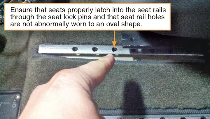
The inspection should start with the cabin door. If the door is hard to open or close, does not fit snugly, or the door latches do not engage or disengage smoothly, the surrounding structure, such as the doorpost, should be inspected for misalignment, which could indicate structural damage. The visual preflight inspection should continue to the interior of the cabin or flight deck where carpeting should be inspected to ensure that it is serviceable, dry, and properly affixed; seat belts and shoulder harnesses should be inspected to ensure that they are free from fraying, latch properly, and are securely attached to their mounting fittings; seats should be inspected to ensure that the seats properly latch into the seat rails through the seat lock pins and that seat rail holes are not abnormally worn to an oval shape; [Figure 5] the windshield and windows should be inspected to ensure that they are clean and free from cracks, and crazing. A dirty, scratched, and/or a severely crazed window can result in near zero visibility due to light refraction at certain angles from the sun.
The AFM/POH or a third party checklist based on the AFM/POH may be used to conduct the visual preflight inspection, and each manufacturer has a specified sequence for conducting the actions. In general, the following items are likely to be included in the AFM/POH preflight inspection:
- Landing gear control is DOWN, if applicable.
- Master, alternator, and magneto switches are OFF.
- Control column locks are REMOVED.
- Fuel selectors should be checked for proper operation in all positions, including the OFF position. Stiff fuel selectors or where the tank position is not legible or lacking detents are unacceptable.
- Trim wheels, which include elevator and may include rudder and aileron, are set for takeoff position.
- Mechanical air-driven gyro instruments should be inspected for signs of hazing on the instrument face, which may indicate leaks.
- Avionics master is OFF.
- Circuit breakers checked IN.
- Confirm that the landing gear handle is in the DOWN position, then turn the master switch ON. Note the fuel quantities on the fuel gauges and compare to the tank level by visual inspection. If so equipped, fuel pumps may be placed in the ON position to verify fuel pressure in the proper operating range.
- Other items may include checking that lights for both the interior and exterior airplane positions are operating and checking any annunciator panels.
- If the airplane has retractable gear, landing gear down and locked lights are checked green.
- Flight instruments should read as follows:
- Airspeed should read zero.
- The altimeter, when properly set to the current barometric setting, should indicate the field elevation within 75 feet for IFR flight.
- If installed, the magnetic compass should indicate the airplane’s direction accurately; and the compass correction card should be legible and complete. For conventional wet magnetic compasses, the instrument face should be clear and the instrument case full of fluid. A cloudy instrument face, bubbles in the fluid, or a partially filled case renders the compass unusable.
- The vertical speed indictor (VSI) should read zero. If the VSI does not show a zero reading, a small screwdriver can be used to zero this instrument if not part of an electronic display. The mechanical VSI is the only flight instrument that a pilot has the prerogative to adjust. All others need to be adjusted by an FAA-certificated repairman or mechanic.
- Avionics master switch ON to check avionics. Avionics master switch OFF, master switch OFF.
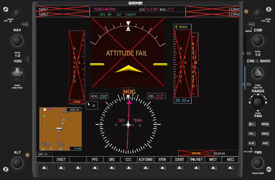
Aircraft equipped with Integrated Flight Deck (IFD) “glass-panel” avionics and supporting systems have specific requirements for checking prior to flight. Ground-based inspections may include verification that the flight deck reference guide is in the aircraft and accessible; checking of system driven removal of “Xs” over engine indicators; checking pitot/static and attitude displays; testing of low level alarms and annunciator panels; setting of fuel levels; and verification that the avionics cooling fans, if equipped, are functional. [Figure 6] The AFM/POH specifies how these preflight inspections are to take place. Since an advanced avionics aircraft preflight checklist may be extensive, pilots should allow time to ensure that all items are properly addressed.
Outer Wing Surfaces and Tail Section
Generally, the AFM/POH specifies a sequence for the pilot to inspect the aircraft that may sequence from the cabin entry access opening and then in a counterclockwise direction until the aircraft has been completely inspected. Besides the AFM/POH preflight assessment, the pilot should also develop awareness for potential areas of concern, such as signs of deterioration or distortion of the structure, whether metal or composite, as well as loose or missing rivets or screws.
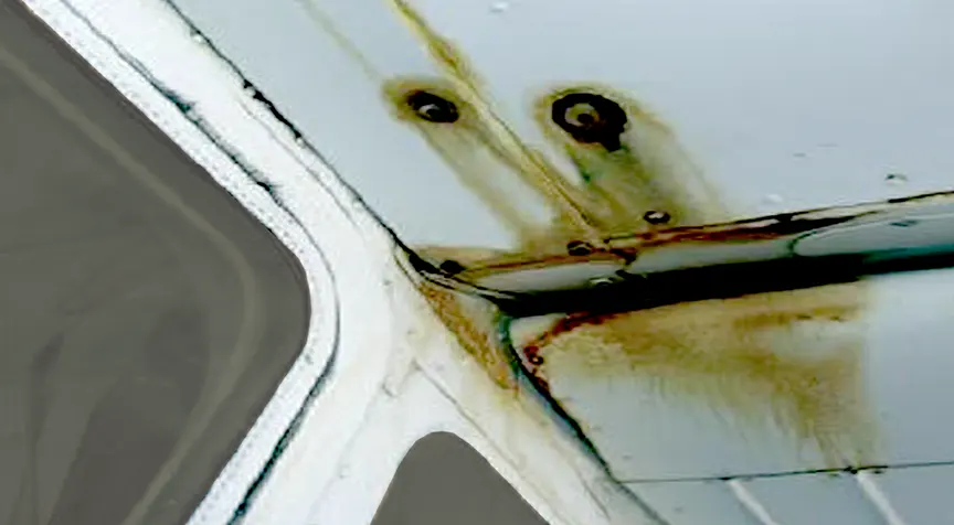
In addition to items specified in the AFM/POH for inspection, the pilot should have an awareness for critical areas, such as spar lines, wing, horizontal, and vertical attach points including wing struts and landing gear attachment areas. The airplane skin should be inspected in these areas as load-related stresses are concentrated along spar lines and attach points. Spar lines are lateral rivet lines that extend across the wing, horizontal stabilizer, or vertical stabilizer. Pilots should pay close attention to spar lines looking for distortion, ripples, bubbles, dents, creases, or waves as any structural deformity may be an indication of internal damage or failure. Inspect around rivet heads looking for cracked paint or a black-oxide film that forms when a rivet works free in its hole. [Figure 7]
Additional areas that should be scrutinized are the leading edges of the wing, horizontal stabilizer, and vertical stabilizer. These areas may have been impact-damaged by rocks, ice, birds, and/or hangar rash incidents. Certain dents and dings may render the structure unairworthy. Some leading edge surfaces have aerodynamic devices, such as stall fences, slots, or vortex generators, and deicing equipment, such as weeping wings and boots. If these items exist on the airplane, the pilot should know their proper condition so that an adequate preflight inspection may occur.
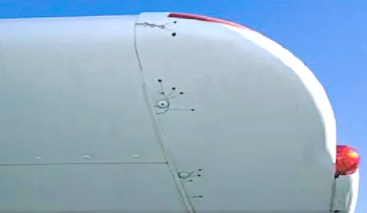
On metal airplanes, wingtips, fairings, and non-structural covers may be fabricated out of thin fiberglass or plastic. These items are frequently affected by cracks radiating from screw holes or concentrated radii. Often, if any of these items are cracked, it is practice to “stop-drill” the crack to prevent crack progression. [Figure 8] Extra care should be exercised to ensure that these devices are in good condition without cracks that may render them unairworthy. Cracks that have continued beyond a stop-drilled location or any new adjacent cracks that have formed may lead to in-flight failure.
Inspecting composite airplanes can be more challenging as the airplanes generally have no rivets or screws to aid the pilot in identifying spar lines and wing attach points. However, delamination of spar to skin or other structural problems may be identified by bubbles, fine hair-line cracks, or changes in sound when gently tapping on the structure with a fingertip. Anything out of place should be addressed by discussing the issue with a properly rated aircraft mechanic.
Fuel and Oil
While there are various formulations of aviation gasoline (AVGAS), only three grades are conventional: 80/87, 100LL, and 100/130. 100LL is the most widely available in the United States. AVGAS is dyed with a faint color for grade identification: 80/87 is dyed red; 100LL is dyed blue; and 100/130 is dyed green. All AVGAS grades have a familiar gasoline scent and texture. 100LL with its blue dye is sometimes difficult to identify unless a fuel sample is held up against a white background in reasonable white lighting.
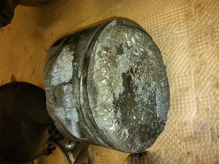
Aircraft piston engines certificated for grade 80/87 run satisfactorily on 100LL if approved as an alternate. The reverse is not true. Fuel of a lower grade should never be substituted for a required higher grade. Detonation will severely damage the engine in a very short period of time. Detonation, as the name suggests, is an explosion of the fuel-air mixture inside the cylinder. During detonation, the fuel/air charge (or pockets within the charge) explodes rather than burns smoothly. Because of this explosion, the charge exerts a much higher force on the piston and cylinder, leading to increased noise, vibration, and cylinder head temperatures. The violence of detonation also causes a reduction in power. Mild detonation may increase engine wear, though some engines can operate with mild detonation regularly. However, severe detonation can cause engine failure in minutes. [Figure 9] Because of the noise that it makes, detonation is “engine knock” or “pinging” in cars.
When approved for the specific airplane to be flown, automobile gasoline is sometimes used as a substitute fuel in certain airplanes. Its use is acceptable only when the particular airplane has been issued a Supplemental Type Certificate (STC) to both the airframe and engine.
Jet fuel is a kerosene-based fuel for turbine engines and a new generation of diesel-powered airplanes. Jet fuel has a stubborn, distinctive, non-gasoline odor and is oily to the touch. Jet fuel is clear or straw-colored, although it may appear dyed when mixed with AVGAS. Jet fuel has disastrous consequences when introduced into AVGAS-burning reciprocating airplane engines. A reciprocating engine operating on jet fuel may start, run, and power the airplane long enough for the airplane to become airborne, only to have the engine fail catastrophically after takeoff.
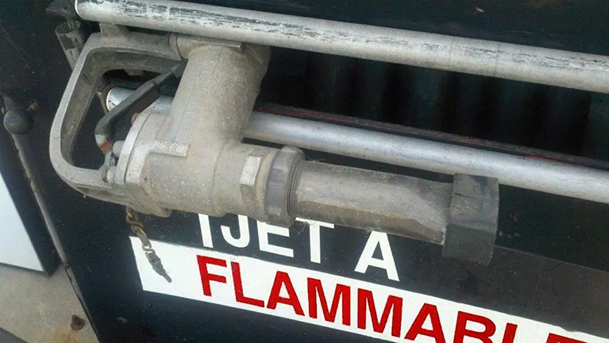
Jet fuel refueling trucks and dispensing equipment are marked with JET-A placards in white characters on a black background. Because of the dire consequences associated with misfueling, fuel nozzles are specific to the type of fuel. AVGAS fuel filler nozzles are straight with a constant diameter. [Figure 10] However, jet fuel filler nozzles are flared at the end to prevent insertion into AVGAS fuel tanks. [Figure 11]

Using the proper, approved grade of fuel is critical for safe, reliable engine operation. Without the proper fuel quantity, grade, and quality, the engine(s) will likely cease to operate. Therefore, it is imperative that the pilot visually verify that the airplane has the correct fuel quantity for the intended flight plus adequate and legal reserves, as well as inspect that the fuel is of the proper grade and that the quality of the fuel is acceptable. The pilot should always ensure that the fuel caps have been securely replaced following each fueling.
Many airplanes experience sensitivity to attitude when fueling for maximum capacity. Nosewheel or main landing gear strut extension, both high as well as low, and the slope of the ramp can significantly alter the attitude of the aircraft and therefore the fuel capacity. Always positively confirm the fuel quantity indicated on the fuel gauges by visually inspecting the level of fuel in each tank.
The pilot should be aware that fuel stains anywhere on the wing or any location where a fuel tank is mounted warrants further investigation—no matter how old the stains appear to be. Fuel stains are a sign of probable fuel leakage. On airplanes equipped with wet-wing fuel tanks, evidence of fuel leakage can be found along rivet lines. [Figure 12]
Checking for water and other sediment contamination is a key preflight item. Water tends to accumulate in fuel tanks from condensation, particularly in partially filled tanks. Because water is heavier than fuel, it tends to collect in the low points of the fuel system. Water can also be introduced into the fuel system from deteriorated gas cap seals exposed to rain or from the supplier’s storage tanks and delivery vehicles. Sediment contamination can arise from dust and dirt entering the tanks during refueling or from deteriorating rubber fuel tanks or tank sealant. Deteriorating rubber from seals and sealant may show up in the fuel sample as small dark specks.
The best preventive measure is to minimize the opportunity for water to condense in the tanks. If possible, the fuel tanks should be completely filled with the proper grade of fuel after each flight, or at least filled after the last flight of the day. The more fuel that is in the tanks, the less room there is for condensation to occur. Keeping fuel tanks filled is also the best way to slow the aging of rubber fuel tanks and tank sealant.
Sufficient fuel should be drained from the fuel strainer quick drain and from each fuel tank sump to check for fuel grade/color, water, dirt, and odor. If water is present, it is usually in bubble or bead-like droplets, different in color (usually clear, sometimes muddy yellow to brown with specks of dirt), in the bottom of the sample jar. In extreme water contamination cases, consider the possibility that the entire fuel sample, particularly if a small sample was taken, is water. If water is found in the first fuel sample, continue sampling until no water and contamination appears. Significant and/or consistent water, sediment or contaminations are grounds for further investigation by qualified maintenance personnel. Each fuel tank sump should be drained during preflight and after refueling. The order of sumping the fuel system is often very important. Check the AFM/POH for specific procedures and order to be followed.
Checking the fuel tank vent is an important part of a preflight assessment. If outside air is unable to enter the tank as fuel is drawn into the engine, the eventual result is fuel starvation and engine failure. During the preflight assessment, the pilot should look for signs of vent damage and blockage. Some airplanes utilize vented fuel caps, fuel vent tubes, or recessed areas under the wings where vents are located. The pilot should use a flashlight to look at the fuel vent to ensure that it is free from damage and clear of obstructions. If there is a rush of air when the fuel tank cap is cracked, there could be a serious problem with the vent system.
Aviation oils are available in various single/multi-grades and mineral/synthetic-based formulations. It is important to use the approved and recommended oil for the engine at all times. The oil not only acts as a lubricant but also as a medium to transfer heat as a result of engine operation and to suspend dirt, combustion byproducts, and wear particles between oil changes. Therefore, the proper level of oil is required to ensure lubrication, effective heat transfer, and the suspension of various contaminants. The oil level should be checked during each preflight, rechecked with each refueling, and maintained to prevent the oil level from falling below the minimum required during engine operation.
During the preflight assessment, if the engine is cold, oil levels on the oil dipstick show higher levels than if the engine was warm and recently shutdown after a flight. When removing the oil dipstick, care should be taken to keep the dipstick from coming in contact with dirty or grimy areas. The dipstick should be inspected to verify the oil level. Typically, piston airplane engines have oil reservoirs with capacities between four and eight quarts, with six quarts being common. Aside from the level of oil, the oil’s color also provides an insight as to its operating condition. Oils darken in color as the oil operating hours increase—this is common and expected as the oil traps contaminants. However, oils that rapidly darken in the first few hours of use after an oil change may indicate engine cylinder problems. Piston airplane engines consume a small amount of oil during normal operation. The amount of consumption varies on many factors; however, if consumption increases or suddenly changes, qualified maintenance personnel should investigate
It is suggested that the critical aspect of fuel and oil not be left to line service personnel without oversight of the pilot responsible for flight. While line personnel are aviation professionals, the pilot is responsible for the safe outcome of any flight. During refueling or when oil is added to an engine, the pilot should monitor and ensure that the correct quantity, quality, and grade of fuel and oil is added and that all fuel and oil caps have been securely replaced.
Landing Gear, Tires, and Brakes
The landing gear, tires, and brakes allow the airplane to maneuver from and return to the ramp, taxiway, and runway environment in a precise and controlled manner. The landing gear, tires, and brakes should be inspected to ensure that the airplane can be positively controlled on the ground. Landing gear on airplanes varies from simple fixed gear to complex retractable gear systems.
Fixed landing gear is a gear system in which the landing gear struts, tires, and brakes are exposed and lend themselves to relatively simple inspection. However, more complex airplanes may have retractable landing gear with multiple tires per landing gear strut, landing gear doors, over-center locks, springs, and electrical squat switches. Regardless of the system, the pilot should follow the AFM/POH during inspection to determine that the landing gear is ready for operation.
On many fixed-gear airplanes, inspection of the landing gear system can be hindered by wheel pants, which are covers used to reduce aerodynamic drag. It is still the pilot’s responsibility to inspect the airplane properly. A flashlight helps the pilot in peering into covered areas. On low-wing airplanes, covered or retraceable landing gear presents additional effort required to crouch below the wing to inspect the landing gear properly.
The following provides guidelines for inspecting the landing gear system; however, the AFM/POH should be the pilot’s reference for the appropriate procedures.
- The pilot, when approaching the airplane, should look at the landing gear struts and the adjacent ground for leaking hydraulic fluid that may be coming from struts, hydraulic lines from landing gear retraction pumps, or from the braking system. Landing gear should be relatively free from grease, oil, and fluid without any undue amounts. Any amount of leaking fluid is unacceptable. In addition, an overview of the landing gear provides an opportunity to verify landing gear alignment and height consistency.
- All landing gear shock struts should also be checked to ensure that they are properly inflated, clean, and free from hydraulic fluid and damage. All axles, links, collars, over-center locks, push rods, forks, and fasteners should be inspected to ensure that they are free from cracks, corrosion, and rust, and are in an airworthy condition.
- Tires should be inspected for proper inflation, an acceptable level of remaining tread, and normal wear pattern. Abnormal wear patterns, sidewall cracks, and damage, such as cuts, bulges, imbedded foreign objects, and visible cords, render the tire unairworthy. For airplanes that are flown by more than one pilot, what happened to the tires on previous flights becomes a significant unknown. Therefore, when possible, the airplane should be moved slightly to allow for evaluation of the complete tire circumference.
- Wheel hubs should be inspected to ensure that they are free from cracks, corrosion, and rust, that all fasteners are secure, and that the air valve stem is straight, capped, and in good condition.
- Brakes and brake systems should be checked to ensure that they are free from rust and corrosion and that all fasteners and safety wires are secure. Brake pads should have a proper amount of material remaining and should be secure. All brake lines should be secure, dry, and free of signs of hydraulic leaks, and devoid of abrasions and deep cracking.
- On tricycle gear airplanes, a shimmy damper is used to damp oscillations of the nose gear and should be inspected to ensure that it is securely attached, is free of hydraulic fluid leaks, and is in overall good condition. Some shimmy dampers do not use hydraulic fluid and instead use an elastomeric compound as the dampening medium. Nose gear links, collars, steering rods, and forks should be inspected to ensure the security of fasteners, minimal free play between torque links, crack-free components, and for proper servicing and general condition.
- On some conventional gear airplanes, those airplanes with a tailwheel or skid, the main landing gear may have bungee cords to help in absorbing landing loads and shocks. The bungee cords must be inspected for security and condition.
- Where the landing gear transitions into the airplane’s structure, the pilot should inspect the attachment points and the airplane skin in the adjacent area—the pilot needs to inspect for wrinkled or other damaged skin, loose bolts, and rivets and verify that the area is free from corrosion.
Engine and Propeller
Properly managing the risks associated with flying requires that the pilot of the airplane identify and mitigate any potential hazards prior to flight to prevent, to the furthest extent possible, a hazard becoming a realized risk. The engine and propeller make up the propulsion system of the airplane—failure of this critical system requires a well-trained and competent pilot to respond with significant time constraints to what is likely to become a major emergency.
The pilot needs to ensure that the engine, propeller, and associated systems are functioning properly prior to operation. This starts with an overview of the cowling that surrounds the airplane engine. The pilot should look for loose, worn, missing, or damaged fasteners, rivets, and latches that secure the cowling around the engine and to the airframe. The pilot should be vigilant as fasteners and rivets can be numerous and surround the cowling requiring a visual inspection from above, the sides, and the bottom. Like other areas on the airframe, rivets should be closely inspected for looseness by looking for signs of a black oxide film around the rivet head. The pilot should pay attention to chipped or flaking paint around rivets and other fasteners as this may be a sign of a lack of security. Any cowling security issues need to be referred to a competent and rated airplane maintenance mechanic.
From the cowling, a general inspection of the propeller spinner, if so equipped, should be completed. Not all airplane/propeller combinations have a spinner, so adherence to the AFM/POH checklist is required. Spinners are subjected to great stresses and should be inspected to be free from dents, cracks, corrosion, and in proper alignment. Cracks may not only occur at locations where fasteners are used but also on the rear-facing spinner plate. In conditions where ice or snow may have entered the spinner around the propeller openings, the pilot should inspect the area to ensure that the spinner is internally free from ice. The engine/propeller/spinner is balanced around the crankshaft and a small amount of ice or snow can produce damaging vibrations. Cracks, missing fasteners, or dents result in a spinner that is unairworthy.
The propeller should be checked for blade erosion, nicks, cracks, pitting, corrosion, and security. On controllable pitch propellers, the propeller hub should be checked for oil leaks that tend to stream directionally from the propeller hub toward the tip. On airplanes so equipped, the alternator/generator drive belts should be checked for proper tension and signs of wear.
When inspecting inside the cowling, the pilot should check all surfaces for oil leaks or deterioration of oil and hydraulic lines, and make certain that the oil cap, filter, oil cooler, and drain plug are secure. The pilot should look for signs of fuel dye, which may indicate a fuel leak. Note that both fuel and oil stains may appear on a cowling inner surface. Observation may be difficult without the aid of a flashlight, so even during day operations, a flashlight is handy when peering into the cowling. The pilot should also check for loose or foreign objects inside the cowling, such as bird nests, shop rags, and/or tools. All visible wires and lines should be checked for security and condition. The exhaust system should be checked for white stains caused by exhaust leaks at the cylinder head or cracks in the exhaust stacks. The heat muffs, which provide cabin heating on some airplanes, should also be checked for general condition and signs of cracks or leaks. An isolated area of oxidized darkened paint on the engine may indicate an area experiencing excessive heat. If visible, the condition of the firewall may be checked for integrity.
The air filter should be checked to ensure that it is free from substantial dirt or restrictions, such as bugs, birds, nests, or other causes of airflow restriction. In addition, air filter elements are made from various materials. In all cases, the element should be free from decomposition and properly serviced.