Most navigation systems approved for en route and terminal operations under IFR, such as VOR, NDB, and GPS, may also be approved to conduct IAPs. The most common systems in use in the United States are the ILS, simplified directional facility (SDF), localizer-type directional aid (LDA), and microwave landing system (MLS). These systems operate independently of other navigation systems. There are new systems being developed, such as WAAS and LAAS. Other systems have been developed for special use.
Instrument Landing Systems (ILS)
 |
| Figure 1. Instrument landing systems |
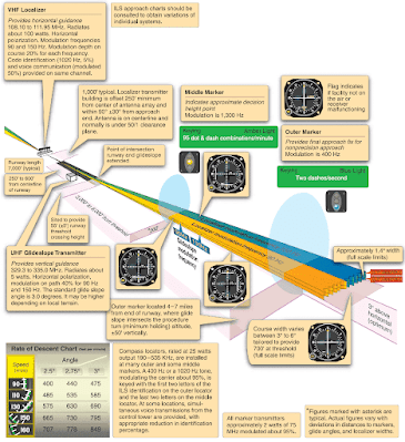
The ILS system provides both course and altitude guidance to a specific runway. The ILS system is used to execute a precision instrument approach procedure or precision approach. [Figure 1] The system consists of the following components:
- A localizer providing horizontal (left/right) guidance along the extended centerline of the runway.
- A glideslope (GS) providing vertical (up/down) guidance toward the runway touchdown point, usually at a 3° slope.
- Marker beacons providing range information along the approach path.
- Approach lights assisting in the transition from instrument to visual flight.
- Compass locators providing transition from en route NAVAIDs to the ILS system and assisting in holding procedures, tracking the localizer course, identifying the marker beacon sites, and providing a FAF for ADF approaches.
- DME collocated with the GS transmitter providing positive distance-to-touchdown information or DME associated with another nearby facility (VOR or standalone), if specified in the approach procedure.
ILS Components
Ground Components
The ILS uses a number of different ground facilities. These facilities may be used as a part of the ILS system, as well as part of another approach. For example, the compass locator may be used with NDB approaches.
Localizer
The localizer (LOC) ground antenna array is located on the extended centerline of the instrument runway of an airport, located at the departure end of the runway to prevent it from being a collision hazard. This unit radiates a field pattern, which develops a course down the centerline of the runway toward the middle markers (MMs) and outer markers (OMs) and a similar course along the runway centerline in the opposite direction. These are called the front and back courses, respectively. The localizer provides course guidance, transmitted at 108.1 to 111.95 MHz (odd tenths only), throughout the descent path to the runway threshold from a distance of 18 NM from the antenna to an altitude of 4,500 feet above the elevation of the antenna site. [Figure 2]
 |
| Figure 2. Localizer coverage limits |
The localizer course width is defined as the angular displacement at any point along the course between a full “fly-left” (CDI needle fully deflected to the left) and a full “fly-right” indication (CDI needle fully deflected to the right). Each localizer facility is audibly identified by a three-letter designator transmitted at frequent regular intervals. The ILS identification is preceded by the letter “I” (two dots). For example, the ILS localizer at Springfield, Missouri, transmits the identifier ISGF. The localizer includes a voice feature on its frequency for use by the associated ATC facility in issuing approach and landing instructions.
The localizer course is very narrow, normally 5°. This results in high needle sensitivity. With this course width, a full-scale deflection shows when the aircraft is 2.5° to either side of the centerline. This sensitivity permits accurate orientation to the landing runway. With no more than one quarter scale deflection maintained, the aircraft will be aligned with the runway.
Glideslope (GS)
GS describes the systems that generate, receive, and indicate the ground facility radiation pattern. The glidepath is the straight, sloped line the aircraft should fly in its descent from where the GS intersects the altitude used for approaching the FAF to the runway touchdown zone. The GS equipment is housed in a building approximately 750 to 1,250 feet down the runway from the approach end of the runway and between 400 and 600 feet to one side of the centerline.
The course projected by the GS equipment is essentially the same as would be generated by a localizer operating on its side. The GS projection angle is normally adjusted to 2.5°to 3.5° above horizontal, so it intersects the MM at about 200 feet and the OM at about 1,400 feet above the runway elevation. At locations where standard minimum obstruction clearance cannot be obtained with the normal maximum GS angle, the GS equipment is displaced farther from the approach end of the runway if the length of the runway permits; or the GS angle may be increased up to 4°.
Unlike the localizer, the GS transmitter radiates signals only in the direction of the final approach on the front course. The system provides no vertical guidance for approaches on the back course. The glidepath is normally 1.4° thick. At 10 NM from the point of touchdown, this represents a vertical distance of approximately 1,500 feet, narrowing to a few feet at touchdown.
Marker Beacons
Two VHF marker beacons, outer and middle, are normally used in the ILS system. [Figure 3] A third beacon, the inner, is used where Category II operations are certified. A marker beacon may also be installed to indicate the FAF on the ILS back course.
 |
| Figure 3. Localizer receiver indications and aircraft displacement |
The OM is located on the localizer front course 4–7 miles from the airport to indicate a position at which an aircraft, at the appropriate altitude on the localizer course, will intercept the glidepath. The MM is located approximately 3,500 feet from the landing threshold on the centerline of the localizer front course at a position where the GS centerline is about 200 feet above the touchdown zone elevation. The inner marker (IM), where installed, is located on the front course between the MM and the landing threshold. It indicates the point at which an aircraft is at the decision height on the glidepath during a Category II ILS approach. The back-course marker, where installed, indicates the back-course FAF.
Compass Locator
Compass locators are low-powered NDBs and are received and indicated by the ADF receiver. When used in conjunction with an ILS front course, the compass locator facilities are collocated with the outer and/or MM facilities. The coding identification of the outer locator consists of the first two letters of the three-letter identifier of the associated LOC. For example, the outer locator at Dallas/Love Field (DAL) is identified as “DA.” The middle locator at DAL is identified by the last two letters “AL.”
Approach Lighting Systems (ALS)
Normal approach and letdown on the ILS is divided into two distinct stages: the instrument approach stage using only radio guidance, and the visual stage, when visual contact with the ground runway environment is necessary for accuracy and safety. The most critical period of an instrument approach, particularly during low ceiling/visibility conditions, is the point at which the pilot must decide whether to land or execute a missed approach. As the runway threshold is approached, the visual glidepath separates into individual lights. At this point, the approach should be continued by reference to the runway touchdown zone markers. The approach lighting system (ALS) provides lights that will penetrate the atmosphere far enough from touchdown to give directional, distance, and glidepath information for safe visual transition.
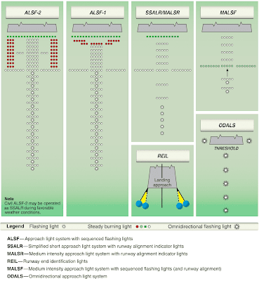
Visual identification of the ALS by the pilot must be instantaneous, so it is important to know the type of ALS before the approach is started. Check the instrument approach chart and the A/FD for the particular type of lighting facilities at the destination airport before any instrument flight. With reduced visibility, rapid orientation to a strange runway can be difficult, especially during a circling approach to an airport with minimum lighting facilities or to a large terminal airport located in the midst of distracting city and ground facility lights. Some of the most common ALS systems are shown in Figure 4.
 |
| Figure 4. Precision and nonprecision ALS configuration |
A high-intensity flasher system, often referred to as “the rabbit,” is installed at many large airports. The flashers consist of a series of brilliant blue-white bursts of light flashing in sequence along the approach lights, giving the effect of a ball of light traveling towards the runway. Typically,“the rabbit” makes two trips toward the runway per second.
Runway end identifier lights (REIL) are installed for rapid and positive identification of the approach end of an instrument runway. The system consists of a pair of synchronized flashing lights placed laterally on each side of the runway threshold facing the approach area.
The visual approach slope indicator (VASI) gives visual descent guidance information during the approach to a runway. The standard VASI consists of light bars that project a visual glidepath, which provides safe obstruction clearance within the approach zone. The normal GS angle is 3°; however, the angle may be as high as 4.5° for proper obstacle clearance. On runways served by ILS, the VASI angle normally coincides with the electronic GS angle. Visual left/right course guidance is obtained by alignment with the runway lights. The standard VASI installation consists of either 2-, 3-, 4-, 6-, 12-, or 16-light units arranged in downwind and upwind light bars. Some airports serving long-bodied aircraft have three-bar VASIs that provide two visual glidepaths to the same runway. The first glidepath encountered is the same as provided by the standard VASI. The second glidepath is about 25 percent higher than the first and is designed for the use of pilots of long-bodied aircraft.
The basic principle of VASI is that of color differentiation between red and white. Each light projects a beam having a white segment in the upper part and a red segment in the lower part of the beam. From a position above the glidepath the pilot sees both bars as white. Lowering the aircraft with respect to the glidepath, the color of the upwind bars changes from white to pink to red. When on the proper glidepath, the landing aircraft will overshoot the downwind bars and undershoot the upwind bars. Thus the downwind (closer) bars are seen as white and the upwind bars as red. From a position below the glidepath, both light bars are seen as red. Moving up to the glidepath, the color of the downwind bars changes from red to pink to white. When below the glidepath, as indicated by a distinct all-red signal, a safe obstruction clearance might not exist. A standard two-bar VASI is illustrated in Figure 5.
 |
| Figure 5. Standard two-bar VASI |
ILS Airborne Components
Airborne equipment for the ILS system includes receivers for the localizer, GS, marker beacons, ADF, DME, and the respective indicator instruments.
The typical VOR receiver is also a localizer receiver with common tuning and indicating equipment. Some receivers have separate function selector switches, but most switch between VOR and LOC automatically by sensing if odd tenths between 108 and 111.95 MHz have been selected. Otherwise, tuning of VOR and localizer frequencies is accomplished with the same knobs and switches, and the CDI indicates “on course” as it does on a VOR radial.
Though some GS receivers are tuned separately, in a typical installation the GS is tuned automatically to the proper frequency when the localizer is tuned. Each of the 40 localizer channels in the 108.10 to 111.95 MHz band is paired with a corresponding GS frequency.
When the localizer indicator also includes a GS needle, the instrument is often called a cross-pointer indicator. The crossed horizontal (GS) and vertical (localizer) needles are free to move through standard five-dot deflections to indicate position on the localizer course and glidepath.
When the aircraft is on the glidepath, the needle is horizontal, overlying the reference dots. Since the glidepath is much narrower than the localizer course (approximately 1.4° from full up to full down deflection), the needle is very sensitive to displacement of the aircraft from on-path alignment. With the proper rate of descent established upon GS interception, very small corrections keep the aircraft aligned.
The localizer and GS warning flags disappear from view on the indicator when sufficient voltage is received to actuate the needles. The flags show when an unstable signal or receiver malfunction occurs.
The OM is identified by a low-pitched tone, continuous dashes at the rate of two per second, and a purple/blue marker beacon light. The MM is identified by an intermediate tone, alternate dots and dashes at the rate of 95 dot/dash combinations per minute, and an amber marker beacon light. The IM, where installed, is identified by a high-pitched tone, continuous dots at the rate of six per second, and a white marker beacon light. The back-course marker (BCM), where installed, is identified by a high-pitched tone with two dots at a rate of 72 to 75 twodot combinations per minute and a white marker beacon light. Marker beacon receiver sensitivity is selectable as high or low on many units. The low-sensitivity position gives the sharpest indication of position and should be used during an approach.
The high-sensitivity position provides an earlier warning that the aircraft is approaching the marker beacon site.
ILS Function
The localizer needle indicates, by deflection, whether the aircraft is right or left of the localizer centerline, regardless of the position or heading of the aircraft. Rotating the OBS has no effect on the operation of the localizer needle, although it is useful to rotate the OBS to put the LOC inbound course under the course index. When inbound on the front course, or outbound on the back course, the course indication remains directional. (See Figure 6, aircraft C, D, and E.)
 |
| Figure 6. Localizer course indications. To follow indications displayed in the aircraft, start from A and proceed through E |
Unless the aircraft has reverse sensing capability and it is in use, when flying inbound on the back course or outbound on the front course, heading corrections to on-course are made opposite the needle deflection. This is commonly described as “flying away from the needle.” (See Figure 6, aircraft A and B.) Back course signals should not be used for an approach unless a back course approach procedure is published for that particular runway and the approach is authorized by ATC.
Once you have reached the localizer centerline, maintain the inbound heading until the CDI moves off center. Drift corrections should be small and reduced proportionately as the course narrows. By the time you reach the OM, your drift correction should be established accurately enough on a wellexecuted approach to permit completion of the approach, with heading corrections no greater than 2°.
The heaviest demand on pilot technique occurs during descent from the OM to the MM, when you maintain the localizer course, adjust pitch attitude to maintain the proper rate of descent, and adjust power to maintain proper airspeed. Simultaneously, the altimeter must be checked and preparation made for visual transition to land or for a missed approach. You can appreciate the need for accurate instrument interpretation and aircraft control within the ILS as a whole, when you notice the relationship between CDI and glidepath needle indications and aircraft displacement from the localizer and glidepath centerlines.
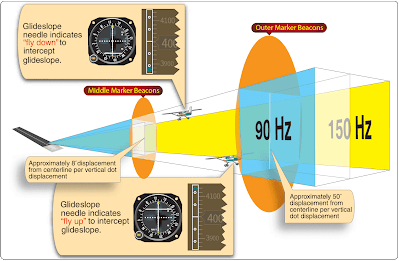
Deflection of the GS needle indicates the position of the aircraft with respect to the glidepath. When the aircraft is above the glidepath, the needle is deflected downward. When the aircraft is below the glidepath, the needle is deflected upward. [Figure 7]
 |
| Figure 7. A GS receiver indication and aircraft displacement. An analog system is on the left and the same indication on the Garmin PFD on the right |
ILS Errors
The ILS and its components are subject to certain errors, which are listed below. Localizer and GS signals are subject to the same type of bounce from hard objects as space waves.
- Reflection. Surface vehicles and even other aircraft flying below 5,000 feet above ground level (AGL) may disturb the signal for aircraft on the approach.
- False courses. In addition to the desired course, GS facilities inherently produce additional courses at higher vertical angles. The angle of the lowest of these false courses occurs at approximately 9°– 12°. An aircraft flying the LOC/GS course at a constant altitude would observe gyrations of both the GS needle and GS warning flag as the aircraft passed through the various false courses. Getting established on one of these false courses results in either confusion (reversed GS needle indications) or in the need for a very high descent rate. However, if the approach is conducted at the altitudes specified on the appropriate approach chart, these false courses are not encountered.
Marker Beacons
The very low power and directional antenna of the marker beacon transmitter ensures that the signal is not received any distance from the transmitter site. Problems with signal reception are usually caused by the airborne receiver not being turned on or by incorrect receiver sensitivity.
Some marker beacon receivers, to decrease weight and cost, are designed without their own power supply. These units utilize a power source from another radio in the avionics stack, often the ADF. In some aircraft, this requires the ADF to be turned on in order for the marker beacon receiver to function, yet no warning placard is required. Another source of trouble may be the “HIGH/LOW/OFF” three-position switch, which both activates the receiver and selects receiver sensitivity. Usually, the “test” feature only tests to see if the light bulbs in the marker beacon lights are working. Therefore, in some installations, there is no functional way for the pilot to ascertain the marker beacon receiver is actually on except to fly over a marker beacon transmitter and see if a signal is received and indicated (e.g., audibly, and visually via marker beacon lights).
Operational Errors
- Failure to understand the fundamentals of ILS ground equipment, particularly the differences in course dimensions. Since the VOR receiver is used on the localizer course, the assumption is sometimes made hat interception and tracking techniques are identical when tracking localizer courses and VOR radials. Remember that the CDI sensing is sharper and faster on the localizer course.
- Disorientation during transition to the ILS due to poor planning and reliance on one receiver instead of on all available airborne equipment. Use all the assistance available; a single receiver may fail.
- Disorientation on the localizer course, due to the first error noted above.
- Incorrect localizer interception angles. A large interception angle usually results in overshooting and possible disorientation. When intercepting, if possible, turn to the localizer course heading immediately upon the first indication of needle movement. An ADF receiver is an excellent aid to orient you during an ILS approach if there is a locator or NDB on the inbound course.
- Chasing the CDI and glidepath needles, especially when you have not sufficiently studied the approach before the flight.
Simplified Directional Facility (SDF)
The simplified directional facility (SDF) provides a final approach course similar to the ILS localizer. The SDF course may or may not be aligned with the runway and the course may be wider than a standard ILS localizer, resulting in less precision. Usable off-course indications are limited to 35° either side of the course centerline. Instrument indications in the area between 35° and 90° from the course centerline are not controlled and should be disregarded.
The SDF must provide signals sufficient to allow satisfactory operation of a typical aircraft installation within a sector which extends from the center of the SDF antenna system to distances of 18 NM covering a sector 10° either side of centerline up to an angle 7° above the horizontal. The angle of convergence of the final approach course and the extended runway centerline must not exceed 30°. Pilots should note this angle since the approach course originates at the antenna site, and an approach continued beyond the runway threshold would lead the aircraft to the SDF offset position rather than along the runway centerline.
The course width of the SDF signal emitted from the transmitter is fixed at either 6° or 12°, as necessary, to provide maximum flyability and optimum approach course quality. A three-letter identifier is transmitted in code on the SDF frequency; there is no letter “I” (two dots) transmitted before the station identifier, as there is with the LOC. For example, the identifier for Lebanon, Missouri, SDF is LBO.
Localizer Type Directional Aid (LDA)
The localizer type directional aid (LDA) is of comparable utility and accuracy to a localizer but is not part of a complete ILS. The LDA course width is between 3° and 6° and thus provides a more precise approach course than an SDF installation. Some LDAs are equipped with a GS. The LDA course is not aligned with the runway, but straight-in minimums may be published where the angle between the runway centerline and the LDA course does not exceed 30°. If this angle exceeds 30°, only circling minimums are published. The identifier is three letters preceded by “I” transmitted in code on the LDA frequency. For example, the identifier for Van Nuys, California, LDA is I-BUR.
Microwave Landing System (MLS)
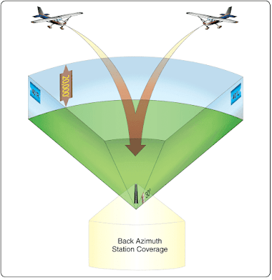
The microwave landing system (MLS) provides precision navigation guidance for exact alignment and descent of aircraft on approach to a runway. It provides azimuth, elevation, and distance. Both lateral and vertical guidance may be displayed on conventional course deviation indicators or incorporated into multipurpose flight deck displays. Range information can be displayed by conventional DME indicators and also incorporated into multipurpose displays. [Figure 8]
 |
| Figure 8. MLS coverage volumes, 3-D representation |
The system may be divided into five functions, which are approach azimuth, back azimuth, approach elevation, range; and data communications. The standard configuration of MLS ground equipment includes an azimuth station to perform functions as indicated above. In addition to providing azimuth navigation guidance, the station transmits basic data, which consists of information associated directly with the operation of the landing system, as well as advisory data on the performance of the ground equipment.
