
Automatic Direction Finder (ADF)
Standard broadcast stations can also be used in conjunction with ADF. Positive identification of all radio stations is extremely important and this is particularly true when using standard broadcast stations for navigation.
NDBs have one advantage over the VOR in that low or medium frequencies are not affected by line-of-sight. The signals follow the curvature of the Earth; therefore, if the aircraft is within the range of the station, the signals can be received regardless of altitude.
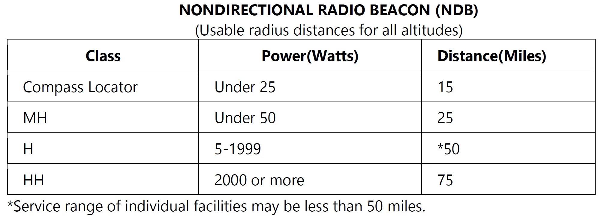
The following table gives the class of NDB stations, their power, and their usable range:
Some of the ADF dials can be rotated to align the azimuth with the aircraft heading; others are fixed with 0° representing the nose of the aircraft and 180° representing the tail. Only the fixed azimuth dial is discussed in this section. [Figure 1]
 |
| Figure 1. ADF with fixed azimuth and magnetic compass |
Figure 2 illustrates terms that are used with the ADF and should be understood by the pilot.
 |
| Figure 2. ADF terms |
To determine the magnetic bearing “FROM” the station, 180° is added to or subtracted from the magnetic bearing to the station. This is the reciprocal bearing and is used when plotting position fixes.
Keep in mind that the needle of fixed azimuth points to the station in relation to the nose of the aircraft. If the needle is deflected 30° to the left for a relative bearing of 330°, this means that the station is located 30° left. If the aircraft is turned left 30°, the needle moves to the right 30° and indicates a relative bearing of 0° meaning that the aircraft is pointing toward the station. If the pilot continues flight toward the station keeping the needle on 0°, the procedure is called homing to the station. If a crosswind exists, the ADF needle continues to drift away from zero. To keep the needle on zero, the aircraft must be turned slightly resulting in a curved flight path to the station. Homing to the station is a common procedure but may result in drifting downwind, thus lengthening the distance to the station.
 |
| Figure 3. ADF tracking |
When tracking away from the station, wind corrections are made similar to tracking to the station, but the ADF needle points toward the tail of the aircraft or the 180° position on the azimuth dial. Attempting to keep the ADF needle on the 180° position during winds results in the aircraft flying a curved flight leading further and further from the desired track. When tracking outbound, corrections for wind should be made in the direction opposite of that in which the needle is pointing.
Although the ADF is not as popular as the VOR for radio navigation, with proper precautions and intelligent use, the ADF can be a valuable aid to navigation.
Global Positioning System
It is not necessary to understand the technical aspects of GPS operation to use it in VFR/IFR navigation. It does differ significantly from conventional, ground-based electronic navigation and awareness of those differences is important. Awareness of equipment approvals and limitations is critical to the safety of flight.
The GPS navigation system broadcasts a signal that is used by receivers to determine precise position anywhere in the world. The receiver tracks multiple satellites and determines a pseudorange measurement to determine the user location. A minimum of four satellites is necessary to establish an accurate three-dimensional position. The Department of Defense (DOD) is responsible for operating the GPS satellite constellation and monitors the GPS satellites to ensure proper operation.
The status of a GPS satellite is broadcast as part of the data message transmitted by the satellite. GPS status information is also available from the U.S. Coast Guard navigation information service at (703) 313-5907 or online at www. navcen.uscg.gov. Additionally, satellite status is available through the NOTAM system.
The GPS receiver verifies the integrity (usability) of the signals received from the GPS constellation through receiver autonomous integrity monitoring (RAIM) to determine if a satellite is providing corrupted information. At least one satellite, in addition to those required for navigation, must be in view for the receiver to perform the RAIM function; thus, RAIM needs a minimum of five satellites in view or four satellites and a barometric altimeter (baro-aiding) to detect an integrity anomaly. For receivers capable of doing so, RAIM needs six satellites in view (or five satellites with baro-aiding) to isolate the corrupt satellite signal and remove it from the navigation solution. Baro-aiding is a method of augmenting the GPS integrity solution by using a nonsatellite input source. GPS derived altitude should not be relied upon to determine aircraft altitude since the vertical error can be quite large and no integrity is provided. To ensure that baro-aiding is available, the current altimeter setting must be entered into the receiver as described in the operating manual.
RAIM messages vary somewhat between receivers; however, generally there are two types. One type indicates that there are not enough satellites available to provide RAIM integrity monitoring and another type indicates that the RAIM integrity monitor has detected a potential error that exceeds the limit for the current phase of flight. Without RAIM capability, the pilot has no assurance of the accuracy of the GPS position.
Selective Availability
With the baseline satellite constellation, users with a clear view of the sky have a minimum of four satellites in view. It is more likely that a user would see six to eight satellites. The satellites broadcast ranging signals and navigation data allowing users to measure their pseudoranges in order to estimate their position, velocity and time, in a passive, listen-only mode. The receiver uses data from a minimum of four satellites above the mask angle (the lowest angle above the horizon at which a receiver can use a satellite). The exact number of satellites operating at any one particular time varies depending on the number of satellite outages and operational spares in orbit. For current status of the GPS constellation, please visit http://tycho.usno.navy.mil/gpscurr.html. [Figure 4]
 |
| Figure 4. Satellite constellation |
VFR Use of GPS
RAIM Capability
In addition, waypoints are added, removed, relocated, or re-named as required to meet operational needs. When using GPS to navigate relative to a named fix, a current database must be used to properly locate a named waypoint. Without the update, it is the pilot’s responsibility to verify the waypoint location referencing to an official current source, such as the Chart Supplement U.S., sectional chart, or en route chart.
In many VFR installations of GPS receivers, antenna location is more a matter of convenience than performance. In IFR installations, care is exercised to ensure that an adequate clear view is provided for the antenna to communicate with satellites. If an alternate location is used, some portion of the aircraft may block the view of the antenna increasing the possibility of losing navigation signal.
This is especially true in the case of hand-held receivers. The use of hand-held receivers for VFR operations is a growing trend, especially among rental pilots. Typically, suction cups are used to place the GPS antennas on the inside of aircraft windows. While this method has great utility, the antenna location is limited by aircraft structure for optimal reception of available satellites. Consequently, signal loss may occur in certain situations where aircraft-satellite geometry causes a loss of navigation signal. These losses, coupled with a lack of RAIM capability, could present erroneous position and navigation information with no warning to the pilot.
While the use of hand-held GPS receivers for VFR operations is not limited by regulation, modification of the aircraft, such as installing a panel- or yoke-mounted holder, is governed by 14 CFR part 43. Pilots should consult a mechanic to ensure compliance with the regulation and a safe installation.
Tips for Using GPS for VFR Operations
While a hand-held GPS receiver can provide excellent navigation capability to VFR pilots, be prepared for intermittent loss of navigation signal, possibly with no RAIM warning to the pilot. If mounting the receiver in the aircraft, be sure to comply with 14 CFR part 43.
Plan flights carefully before taking off. If navigating to user-defined waypoints, enter them prior to flight, not on the fly. Verify the planned flight against a current source, such as a current sectional chart. There have been cases in which one pilot used waypoints created by another pilot that were not where the pilot flying was expecting. This generally resulted in a navigation error. Minimize head-down time in the aircraft and maintain a sharp lookout for traffic, terrain, and obstacles. Just a few minutes of preparation and planning on the ground makes a great difference in the air.
Another way to minimize head-down time is to become very familiar with the receiver’s operation. Most receivers are not intuitive. The pilot must take the time to learn the various keystrokes, knob functions, and displays that are used in the operation of the receiver. Some manufacturers provide computer-based tutorials or simulations of their receivers. Take the time to learn about the particular unit before using it in flight.
In summary, be careful not to rely on GPS to solve all VFR navigational problems. Unless an IFR receiver is installed in accordance with IFR requirements, no standard of accuracy or integrity can be assured. While the practicality of GPS is compelling, the fact remains that only the pilot can navigate the aircraft, and GPS is just one of the pilot’s tools to do the job.
VFR Waypoints
When filing VFR flight plans, use the five-letter identifier as a waypoint in the route of flight section if there is an intended course change at that point or if used to describe the planned route of flight. This VFR filing would be similar to VOR use in a route of flight. Pilots must use the VFR waypoints only when operating under VFR conditions.
Any VFR waypoints intended for use during a flight should be loaded into the receiver while on the ground and prior to departure. Once airborne, pilots should avoid programming routes or VFR waypoint chains into their receivers.
Pilots should be especially vigilant for other traffic while operating near VFR waypoints. The same effort to see and avoid other aircraft near VFR waypoints is necessary, as is the case when operating near VORs and NDBs. In fact, the increased accuracy of navigation through the use of GPS demands even greater vigilance as there are fewer off-course deviations among different pilots and receivers. When operating near a VFR waypoint, use all available ATC services, even if outside a class of airspace where communications are required. Regardless of the class of airspace, monitor the available ATC frequency closely for information on other aircraft operating in the vicinity. It is also a good idea to turn on landing light(s) when operating near a VFR waypoint to make the aircraft more conspicuous to other pilots, especially when visibility is reduced.