En route instrument flight rules (IFR) navigation is evolving from the ground-based navigational aid (NAVAID) airway system to a sophisticated satellite and computer-based system that can generate courses to suit the operational requirements of almost any flight. The FAA Global Navigation Satellite System (GNSS) provides satellite-based positioning, navigation, and timing services in the United States to enable performance-based operations for all phases of flight, to include en route navigation.
14 CFR Part 91, § 91.181, is the basis for the course to be flown. Unless authorized by ATC, to operate an aircraft within controlled airspace under IFR, pilots must either fly along the centerline when on a Federal airway or, on routes other than Federal airways, along the direct course between NAVAIDs or fixes defining the route. The regulation allows maneuvering to pass well clear of other air traffic or, if in visual meteorogical conditions (VMC), to clear the flightpath both before and during climb or descent.
Airways
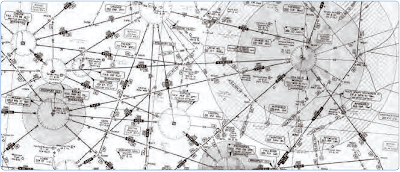
Airway routing occurs along pre-defined pathways called airways. [Figure 1] Airways can be thought of as three- dimensional highways for aircraft. In most land areas of the world, aircraft are required to fly airways between the departure and destination airports. The rules governing airway routing, Standard Instrument Departures (SID) and Standard Terminal Arrival (STAR), are published flight procedures that cover altitude, airspeed, and requirements for entering and leaving the airway. Most airways are eight nautical miles (14 kilometers) wide, and the airway flight levels keep aircraft separated by at least 500 vertical feet from aircraft on the flight level above and below when operating under VFR.
When operating under IFR, between the surface and an altitude of Flight Level (FL) 290, no aircraft should come closer vertically than 1,000 feet. Above FL 290, no aircraft should come closer than 2,000 feet except in airspace where Reduced Vertical Separation Minima (RVSM) can be applied in which case the vertical separation is reduced to 1,000 feet. Airways usually intersect at NAVAIDs that designate the allowed points for changing from one airway to another. Airways have names consisting of one or more letters followed by one or more digits (e.g., V484 or UA419).
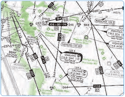
The en route airspace structure of the National Airspace System (NAS) consists of three strata. The first stratum low altitude airways in the United States can be navigated using NAVAIDs, have names that start with the letter V, and are called Victor Airways. [Figure 2] They cover altitudes from approximately 1,200 feet above ground level (AGL) up to, but not including 18,000 feet above mean sea level (MSL). The second stratum high altitude airways in the United States all have names that start with the letter J, and are called Jet Routes. [Figure 3] These routes run from 18,000 feet to 45,000 feet. The third stratum allows random operations above flight level (FL) 450. The altitude separating the low and high airway structure varies from county to country. For example, in Switzerland it is 19,500 feet and 25,000 feet in Egypt.
 |
| Figure 2. Victor airways |
 |
| Figure 3. Jet routes |
Air Route Traffic Control Centers
The FAA defines an Air Route Traffic Control Center (ARTCC) as a facility established to provide air traffic control (ATC) service to aircraft operating on IFR flight plans within controlled airspace, principally during the en route phase of flight. When equipment capabilities and controller workload permit, certain advisory/assistance services may be provided to VFR aircraft.
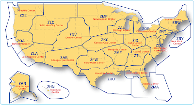
ARTCCs, usually referred to as Centers, are established primarily to provide air traffic service to aircraft operating on IFR flight plans within the controlled airspace, and principally during the en route phase of flight. There are 21 ARTCC’s in the United States. [Figure 4] Any aircraft operating under IFR within the confines of an ARTCC’s airspace is controlled by air traffic controllers at the Center. This includes all sorts of different types of aircraft: privately owned single engine aircraft, commuter airlines, military jets, and commercial airlines.
 |
| Figure 4. Air Route Traffic Control Centers |
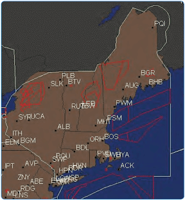
The largest component of the NAS is the ARTCC. Each ARTCC covers thousands of square miles encompassing all or part of several states. ARTCCs are built to ensure safe and expeditious air travel. All Centers operate 7-days a week, 24-hours a day, and employ a combination of several hundred ATC specialists, electronic technicians, computer system specialists, environmental support specialists, and administrative staff. Figure 5 is an example of the Boston ARTCC. The green lines mark the boundaries of the Boston Center area, and the red lines mark the boundaries of Military Operations Areas (MOAs), Prohibited, Restricted, Alert, and Warning Areas.
 |
| Figure 5. Boston Air Route Traffic Control Center |
Safe Separation Standards
The primary means of controlling aircraft is accomplished by using highly sophisticated computerized radar systems. In addition, the controller maintains two-way radio communication with aircraft in his or her sector. In this way, the specialist ensures that the aircraft are separated by the following criteria:
- Laterally—5 miles
- Vertically—
- 1,000 feet (if the aircraft is below FL 290, or between FL 290 and FL 410 for RVSM compliant aircraft)
- 2,000 feet (if the aircraft is at FL 290 or above)
The controllers can accomplish this separation by issuing instructions to the pilots of the aircraft involved. Altitude assignments, speed adjustments, and radar vectors are examples of instructions that might be issued to aircraft.
En route control is handled by pinpointing aircraft positions through the use of flight progress strips. These strips are pieces of printed paper containing pertinent information extracted from the pilot’s flight plan. These strips are printed 20 minutes prior to an aircraft reaching each Center’s sector. A flight progress strip tells the controller everything needed to direct that aircraft. If the flight progress strips of each aircraft approaching a sector are arranged properly, it is possible to determine potential conflicts long before the aircraft are even visible on the Center controller’s display. In areas where radar coverage is not available, this is the sole means of separating aircraft.
The strips, one for each en route point from which the pilot reports his or her position, are posted on a slotted board in front of the air traffic controller. [Figure 6] At a glance, he or she is able to see certain vital data: the type of aircraft and who is flying it (airline, business, private, or military pilot), aircraft registration number or flight number, route, speed, altitude, airway designation, and the estimated time of arrival (ETA) at destination. As the pilot calls in the aircraft’s position and time at a predetermined location, the strips are removed from their slots and filed. Any change from the original flight plan is noted on the strips as the flight continues. Thus, from a quick study of the flight progress board, a controller can assess the overall traffic situation and can avoid possible conflicts.
 |
| Figure 6. Flight progress strips |
Figure 7 shows the Fort Worth, Texas Air Route Traffic Control Center (ZFW) and the geographical area that it covers. The Center has approximately 350 controllers. Most are certified and some are in on-the-job training.
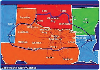 |
| Figure 7. Fort Worth Air Route Traffic Control Center |
Sectors
The airspace controlled by a Center may be further administratively subdivided into smaller, manageable pieces of airspace called sectors. A few sectors extend from the ground up, but most areas are stratified into various levels to accommodate a wide variety of traffic. Each sector is staffed by a set of controllers and has a unique radio frequency that the controller uses to communicate with the pilots. As aircraft transition from one sector to another, they are instructed to change to the radio frequency used by the next sector. Each sector also has secure landline communications with adjacent sectors, approach controls, areas, ARTCCs, flight service centers, and military aviation control facilities.
The ARTCC at Fort Worth, Texas is subdivided into sectors that are categorized as follows:
- Eighteen low altitude sectors. [Figure 8]
- Seven intermediate altitude sectors. [Figure 9]
- Sixteen high altitude sectors. [Figure 10]
- One ultra high altitude sector. [Figure 11]
 |
| Figure 8. Low altitude sectors |
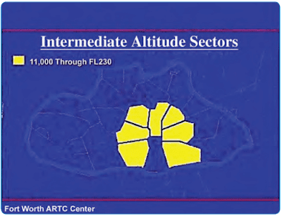 |
| Figure 9. Intermediate altitude sectors |
 |
| Figure 10. High altitude sectors |
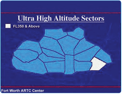 |
| Figure 11. Ultra high altitude sectors |
From one to three controllers may work a sector, depending upon the amount of air traffic. Each controller is assigned to work the positions within an area of specialization. Controllers have direct communication with pilots, with surrounding sectors and Centers, plus the towers and Flight Service Stations (FSS) under their jurisdiction. Each control position is equipped with computer input and readout devices for aircraft flight plan data.
The Center controllers have many decision support tools (computer software programs) that provide vital information to assist the controllers in maintaining safe separation distances for all aircraft flying through their sector. For example, one tool available allows the controller to display the extended route of any aircraft on the radar screen called a vector line. This line projects where the aircraft will be within a specified number of minutes, assuming the aircraft does not change its course. This is a helpful tool to determine if aircraft flying intersecting routes pass safely within the separation standard, or if they conflict with each other. In addition to vector lines, the controller can also display a route line for any given aircraft on his or her radar screen. This tells the controller where a particular aircraft is in specified number of minutes, as well as the path the aircraft will fly to get there. Decision support tools such as these help each controller look ahead and avoid conflicts.
In-flight Requirements and Instructions
The CFRs require the pilot in command under IFR in controlled airspace to continuously monitor an appropriate Center or control frequency. When climbing after takeoff, an IFR flight is either in contact with a radar-equipped local departure control or, in some areas, an ARTCC facility. As a flight transitions to the en route phase, pilots typically expect a handoff from departure control to a Center frequency if not already in contact with the Center.
The FAA National Aeronautical Information Services publishes en route charts depicting Centers and sector frequencies. [Figure 12] During handoff from one Center to another, the previous controller assigns a new frequency. In cases where flights may be out of range, the Center frequencies on the face of the chart are very helpful. In Figure 12, notice the boundary between Memphis, Tennessee and Atlanta, Georgia Centers, and the remote sites with discrete very high frequency (VHF) and ultra high frequency (UHF) for communicating with the appropriate ARTCC. These Center frequency boxes can be used for finding the nearest frequency within the aircraft range. They also can be used for making initial contact with the Center for clearances. The exact location for the Center transmitter is not shown, although the frequency box is placed as close as possible to the known location.
 |
| Figure 12. Air Route Traffic Control Centers and sector frequencies |
During the en route phase, as a flight transitions from one Center facility to the next, a handoff or transfer of control is required as previously described. The handoff procedure is similar to the handoff between other radar facilities, such as departure or approach control. During the handoff, the controller whose airspace is being vacated issues instructions that include the name of the facility to contact, appropriate frequency, and other pertinent remarks.
Accepting radar vectors from controllers does not relieve pilots of their responsibility for safety of flight. Pilots must maintain a safe altitude and keep track of their position, and it is their obligation to question controllers, request an amended clearance, or, in an emergency, deviate from their instructions if they believe that the safety of flight is in doubt. Keeping track of altitude and position when climbing, and during all other phases of flight, are basic elements of situational awareness (SA). Aircraft equipped with an enhanced ground proximity warning system (EGPWS), terrain awareness and warning system (TAWS), or traffic alert and collision avoidance system (TCAS) help pilots detect and/or correct for potential unsafe proximities to other aircraft and increases pilot(s) situational awareness. Regardless of equipment, pilots must always maintain SA regarding their location and the location of traffic in their vicinity.
High Altitude Area Navigation Routing
Special high altitude routes allow pilots routing options for flight within the initial high altitude routing (HAR) Phase I expansion airspace. Pilots are able to fly user-preferred routes, referred to as non-restrictive routing (NRR), between specific fixes described by pitch (entry into) and catch (exit out of) fixes in the HAR airspace. Pitch points indicate an end of departure procedures, preferred IFR routings, or other established routing programs where a flight can begin a segment of NRR. The catch point indicates where a flight ends a segment of NRR and joins published arrival procedures, preferred IFR routing, or other established routing programs.
The HAR Phase I expansion airspace is defined as that airspace at and above FL 350 in fourteen of the western and southern ARTCCs. The airspace includes Minneapolis (ZMP), Chicago (ZAU), Kansas City (ZKC), Denver (ZDV), Salt Lake City (ZLC), Oakland (ZOA), Seattle Centers (ZSE), Los Angeles (ZLA), Albuquerque (ZAB), Fort Worth (ZFW), Memphis (ZME), and Houston (ZHU). Jacksonville (ZJX) and Miami (ZMA) are included for east-west routes only. To develop a flight plan, select pitch and catch points which can be found in the Chart Supplement (CS) based upon your desired route across the Phase I airspace. Filing requirements to pitch points, and from catch points, remain unchanged from current procedures. For the portion of the route between the pitch and catch points, NRR is permitted. Where pitch points for a specific airport are not identified, aircraft should file an appropriate departure procedure (DP), or any other user preferred routing prior to the NRR portion of their routing. Where catch points for a specific airport are not identified aircraft should file, after the NRR portion of their routing, an appropriate arrival procedure or other user preferred routing to their destination.
Additionally, information concerning the location and schedule of special use airspace (SUA) and Air Traffic Control Assigned Airspace (ATCAA) can be found at http:// sua.faa.gov. ATCAA refers to airspace in the high altitude structure supporting military and other special operations. Pilots are encouraged to file around these areas when they are scheduled to be active, thereby avoiding unplanned reroutes around them.
In conjunction with the HAR program, area navigation (RNAV) routes have been established to provide for a systematic flow of air traffic in specific portions of the en route flight environment. The designator for these RNAV routes begin with the letter Q, for example, Q-501. Where those routes aid in the efficient orderly management of air traffic, they are published as preferred IFR routes.
Preferred IFR Routes
Preferred IFR routes are established between busier airports to increase system efficiency and capacity. They normally extend through one or more ARTCC areas and are designed to achieve balanced traffic flows among high density terminals. IFR clearances are issued on the basis of these routes except when severe weather avoidance procedures or other factors dictate otherwise. Preferred IFR routes are listed in the CS and can also be found on www.fly.faa.gov, which requires entering the following data: departure airport designator, destination, route type, area, aircraft types, altitude, route string, direction, departure ARTCC, and arrival ARTCC. [Figure 13] If a flight is planned to or from an area having such routes but the departure or arrival point is not listed in the CS, pilots may use that part of a preferred IFR route that is appropriate for the departure or arrival point listed. Preferred IFR routes are correlated with departure procedures (DPs) and STARs and may be defined by airways, jet routes, direct routes between NAVAIDs, waypoints, NAVAID radials/ distance measuring equipment (DME), or any combinations thereof.
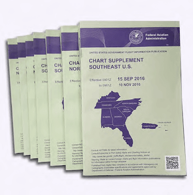 |
| Figure 13. Chart Supplement (includes Airport/Facility Directory section) |
Preferred IFR routes are published in the CS for the low and high altitude stratum. If they begin or end with an airway number, it indicates that the airway essentially overlies the airport and flights normally are cleared directly on the airway. Preferred IFR routes beginning or ending with a fix indicate that pilots may be routed to or from these fixes via a SID route, radar vectors, or a STAR. Routes for major terminals are listed alphabetically under the name of the departure airport. Where several airports are in proximity, they are listed under the principal airport and categorized as a metropolitan area (e.g., New York Metro Area). One way preferred IFR routes are listed is numerically, showing the segment fixes and the direction and times effective. Where more than one route is listed, the routes have equal priority for use. Official location identifiers are used in the route description for very high frequency omnidirectional ranges (VORs) and very high frequency omnidirectional ranges/ tactical air navigation (VORTACs), and intersection names are spelled out. The route is direct where two NAVAIDs, an intersection and a NAVAID, a NAVAID and a NAVAID radial and distance point, or any navigable combination of these route descriptions follow in succession.
A system of preferred IFR routes helps pilots, flight crews, and dispatchers plan a route of flight to minimize route changes, and to aid in the efficient, orderly management of air traffic using Federal airways. Preferred IFR routes are designed to serve the needs of airspace users and to provide for a systematic flow of air traffic in the major terminal and en route flight environments. Cooperation by all pilots in filing preferred routes results in fewer air traffic delays and better efficiency for departure, en route, and arrival air traffic service. [Figure 14]
 |
| Figure 14. Preferred IFR routes |
Substitute Airway or Route Structures
ARTCCs are responsible for specifying essential substitute airway or route segments (sub-routes) and fixes for use during scheduled or unscheduled VOR/VORTAC shutdowns. Scheduled shutdowns of navigational facilities require planning and coordination to ensure an uninterrupted flow of air traffic. Aeronautical Information Services, in coordination with the ARTCCs, determine when the length of outages or other factors require publication of sub-routes and Flight Program Operations (AJW-3) provides flight inspection services, obstacle clearance verification, certification, and final approval of substitute routes.
Substitute Airway En Route Flight Procedures
A schedule of proposed facility shutdowns within the region is maintained and forwarded as far in advance as possible to enable the substitute routes to be published. Substitute routes are normally based on VOR/VORTAC facilities established and published for use in the appropriate altitude strata. In the case of substitute routes in the upper airspace stratum, it may be necessary to establish routes by reference to VOR/VORTAC facilities used in the low altitude system. Non-directional (radio) beacon (NDB) facilities may only be used where VOR/VORTAC coverage is inadequate and ATC requirements necessitate use of such NAVAIDs. Where operational necessity dictates, NAVAIDs may be used beyond their standard service volume (SSV) limits that define the reception limits of unrestricted NAVAIDs, which are usable for random/unpublished route navigation, provided that the routes can be given adequate frequency protection.
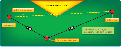
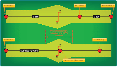
The centerline of substitute routes must be contained within controlled airspace [Figure 15], although substitute routes for off-airway routes may not be in controlled air-space. [Figure 16] Substitute routes are flight inspected to verify clearance of controlling obstacles and to check for satisfactory facility performance. If substitute routes do not overlie existing routes, or are wider than existing routes, map studies are required to identify controlling obstacles. [Figure 17] The format for describing substitute routes is from navigational fix to navigational fix. A minimum en route altitude (MEA) and a maximum authorized altitude (MAA) are provided for each route segment. Temporary reporting points may be substituted for the out-of-service facility and only those other reporting points that are essential for ATC. Normally, temporary reporting points over intersections are not necessary where Center radar coverage exists. A minimum reception altitude (MRA) is established for each temporary reporting point.
 |
| Figure 15. 14 CFR Part 95 sub-routes |
 |
| Figure 16. Non-Part 95 sub-routes |
 |
| Figure 17. Sub-route wider than existing route |
Tower En Route Control
Tower en route control (TEC) is an ATC program available to pilots that provides a service to aircraft proceeding to and from metropolitan areas. It links designated approach control areas by a network of identified routes made up of the existing airway structure of the NAS, which makes it possible to fly an IFR flight without leaving approach control airspace. [Figure 18] This service is designed to help expedite air traffic and reduces ATC and pilot communication requirements. The program is generally used by non-turbojet aircraft operating at and below 10,000 feet but a few facilities, such as Milwaukee and Chicago, have allowed turbojets to proceed between city pairs. Participating flights are relatively short with a duration of two hours or less.
 |
| Figure 18. Tower En Route Control (TEC) Northeast U.S. (Eastern) |
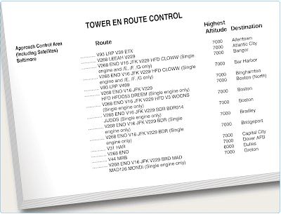
TEC is referred to as tower en route, or tower-to-tower, and allows flight beneath the en route structure. TEC reallocates airspace both vertically and geographically to allow flight planning between city pairs while remaining with approach control airspace. All users are encouraged to use the TEC route descriptions located in the CS when filing flight plans. [Figure 19] All published TEC routes are designed to avoid en route airspace, and the majority is within radar coverage.
 |
| Figure 19. Chart Supplement (NE), Tower En Route Control route descriptions (Baltimore) |
Tower En Route Control Route Descriptions
The graphic depiction of TEC routes located in the CS is not to be used for navigation or for detailed flight planning because not all city pairs are depicted. The information is intended to show geographic areas connected by TEC. [Figure 18] Pilots should refer to the route descriptions for specific flight planning.
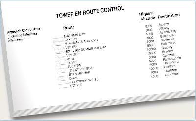
As shown in Figure 19, the route description contains four columns of information. The first column is the approach control area within which the departure airport is located, which are listed alphabetically. The second column shows the specific route, airway, or radial that is to be used. The third column shows the highest altitude allowed for the route, and the fourth shows the destination airport, which are also listed alphabetically. When flight planning, it is important to always check current publications for information about the departure and destination airport. Routes are effective only during each respective terminal facilities normal operating hours. Always check NOTAMs to ensure that appropriate terminal facilities are operating for the planned flight time. Altitudes are always listed in thousands of feet. ATC may request that the pilot changes altitude while in flight in order to maintain the flight within approach control airspace. ATC provides radar monitoring and, if necessary, course guidance if the highest altitude assigned is below the MEA.
Shown in Figure 20, under the second column, the word “Direct” appears as the route when radar vectors are used or no airway exists. This also indicates that a SID or STAR may be assigned by ATC. When a NAVAID or intersection identifier appears with no airway immediately preceding or following the identifier, the routing is understood to be direct to or from that point unless otherwise cleared by ATC. Routes beginning and ending with an airway indicate that the airway essentially overflies the airport, or radar vectors are issued. [Figure 20] Where more than one route is listed to the same destination, ensure that the correct route for the type of aircraft classification has been filed. These are denoted after the route in the altitude column using J (jet powered), M (turbo props/special, cruise speed 190 knots or greater), P (non-jet, cruise speed 190 knots or greater), or Q (non-jet, cruise speed 189 knots or less). [Figure 21] Although all airports are not listed under the destination column, IFR flights may be planned to satellite airports in the proximity of major airports via the same routing. When filing flight plans, the coded route identifier (i.e., BURL 1, VTUL4, or POML3) may be used in lieu of the route of flight.
 |
| Figure 20. Chart Supplement (NE), Tower En Route Control route descriptions (Allentown) |
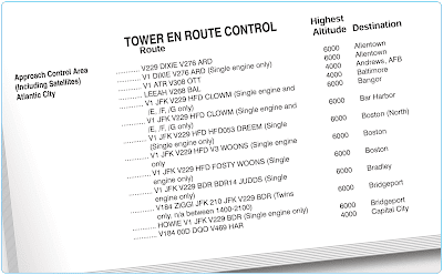 |
| Figure 21. Chart Supplement (NE), Tower En Route Control route descriptions (Atlantic City) |

