There are multiple applications for hydraulic use in aircraft, depending on the complexity of the aircraft. For example, a hydraulic system is often used on small airplanes to operate wheel brakes, retractable landing gear, and some constant-speed propellers. On large airplanes, a hydraulic system is used for flight control surfaces, wing flaps, spoilers, and other systems.
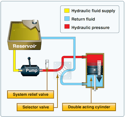
A basic hydraulic system consists of a reservoir, pump (either hand, electric, or engine-driven), a filter to keep the fluid clean, a selector valve to control the direction of flow, a relief valve to relieve excess pressure, and an actuator. [Figure 1]
 |
| Figure 1. Basic hydraulic system |
The hydraulic fluid is pumped through the system to an actuator or servo. A servo is a cylinder with a piston inside that turns fluid power into work and creates the power needed to move an aircraft system or flight control. Servos can be either single-acting or double-acting, based on the needs of the system. This means that the fluid can be applied to one or both sides of the servo, depending on the servo type. A single-acting servo provides power in one direction. The selector valve allows the fluid direction to be controlled. This is necessary for operations such as the extension and retraction of landing gear during which the fluid must work in two different directions. The relief valve provides an outlet for the system in the event of excessive fluid pressure in the system. Each system incorporates different components to meet the individual needs of different aircraft.
A mineral-based hydraulic fluid is the most widely used type for small aircraft. This type of hydraulic fluid, a kerosene-like petroleum product, has good lubricating properties, as well as additives to inhibit foaming and prevent the formation of corrosion. It is chemically stable, has very little viscosity change with temperature, and is dyed for identification. Since several types of hydraulic fluids are commonly used, an aircraft must be serviced with the type specified by the manufacturer. Refer to the AFM/POH or the Maintenance Manual.
Landing Gear
The landing gear forms the principal support of an aircraft on the surface. The most common type of landing gear consists of wheels, but aircraft can also be equipped with floats for water operations or skis for landing on snow. [Figure 2] The landing gear on small aircraft consists of three wheels: two main wheels (one located on each side of the fuselage) and a third wheel positioned either at the front or rear of the airplane. Landing gear employing a rear-mounted wheel is called conventional landing gear. Airplanes with conventional landing gear are often referred to as tailwheel airplanes. When the third wheel is located on the nose, it is called a nosewheel, and the design is referred to as a tricycle gear. A steerable nosewheel or tailwheel permits the airplane to be controlled throughout all operations while on the ground.
 |
| Figure 2. The landing gear supports the airplane during the takeoff run, landing, taxiing, and when parked |
Tricycle Landing Gear
There are three advantages to using tricycle landing gear:
- It allows more forceful application of the brakes during landings at high speeds without causing the aircraft to nose over.
- It permits better forward visibility for the pilot during takeoff, landing, and taxiing.
- It tends to prevent ground looping (swerving) by providing more directional stability during ground operation since the aircraft’s center of gravity (CG) is forward of the main wheels. The forward CG keeps the airplane moving forward in a straight line rather than ground looping.
Nosewheels are either steerable or castering. Steerable nosewheels are linked to the rudders by cables or rods, while castering nosewheels are free to swivel. In both cases, the aircraft is steered using the rudder pedals. Airplanes with a castering nosewheel may require the pilot to combine the use of the rudder pedals with independent use of the brakes.
Tailwheel Landing Gear
Tailwheel landing gear airplanes have two main wheels attached to the airframe ahead of its CG that support most of the weight of the structure. A tailwheel at the very back of the fuselage provides a third point of support. This arrangement allows adequate ground clearance for a larger propeller and is more desirable for operations on unimproved fields. [Figure 3]
 |
| Figure 3. Tailwheel landing gear |
With the CG located behind the main landing gear, directional control using this type of landing gear is more difficult while on the ground. This is the main disadvantage of the tailwheel landing gear. For example, if the pilot allows the aircraft to swerve while rolling on the ground at a low speed, he or she may not have sufficient rudder control and the CG will attempt to get ahead of the main gear, which may cause the airplane to ground loop.
Diminished forward visibility when the tailwheel is on or near the ground is a second disadvantage of tailwheel landing gear airplanes. Because of these disadvantages, specific training is required to operate tailwheel airplanes.
Fixed and Retractable Landing Gear
Landing gear can also be classified as either fixed or retractable. Fixed landing gear always remains extended and has the advantage of simplicity combined with low maintenance. Retractable landing gear is designed to streamline the airplane by allowing the landing gear to be stowed inside the structure during cruising flight. [Figure 4]
 |
| Figure 4. Fixed (left) and retractable (right) gear airplanes |
Brakes
Airplane brakes are located on the main wheels and are applied by either a hand control or by foot pedals (toe or heel). Foot pedals operate independently and allow for differential braking. During ground operations, differential braking can supplement nosewheel/tailwheel steering.
