The turbopropeller-powered airplane flies and handles just like any other airplane of comparable size and weight, since the aerodynamics are the same. The major differences between flying a turboprop and other non-turbine-powered airplanes are found in the handling of the airplane’s powerplant and its associated systems, which are unique to gas turbine engines. The turbopropellerpowered airplane also has the advantage of being equipped with a constant speed, full feathering and reversing propeller—something normally not found on piston-powered airplanes.
Gas Turbine Engine
Both piston (reciprocating) engines and gas turbine engines are internal combustion engines. They have a similar cycle of operation that consists of induction, compression, combustion, expansion, and exhaust. In a piston engine, each of these events is a separate distinct occurrence in each cylinder. Also in a piston engine, an ignition event occurs during each cycle in each cylinder. Unlike reciprocating engines, in gas turbine engines these phases of power occur simultaneously and continuously instead of successively one cycle at a time. Additionally, ignition occurs during the starting cycle and is continuous thereafter. The basic gas turbine engine contains four sections: intake, compression, combustion, and exhaust. [Figure 1]
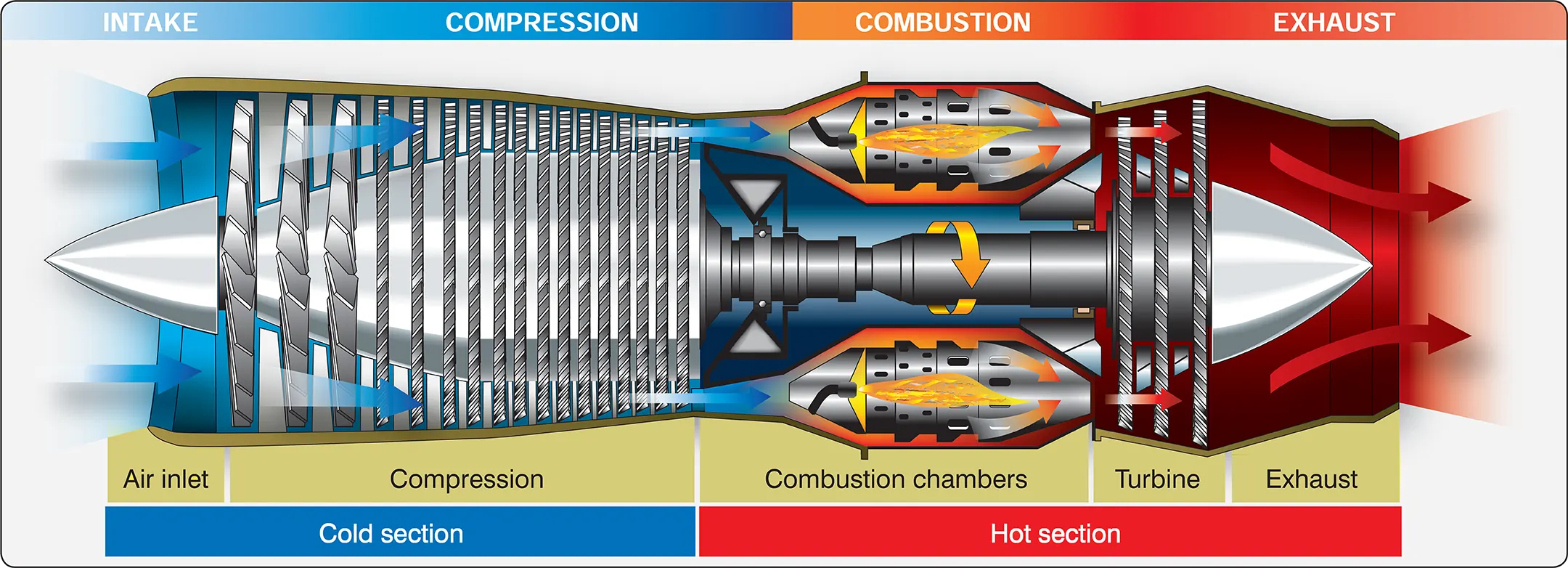
To start a gas turbine engine, the compressor section is normally rotated by an electric starter. As compressor revolutions per minute (rpm) increase, air flowing through the inlet is compressed to a high pressure, delivered to the combustion section, and ignited. In gas turbine engines, not all of the compressed air is used to support combustion. Some of the compressed air bypasses the burner section within the engine to provide internal cooling. The fuel/air mixture in the combustion chamber burns in a continuous combustion process and produces a very high temperature, typically around 4,000° Fahrenheit (F). When this hot air mixes with bypass air, the temperature of the mixed air mass drops to 1,600 – 2,400 °F.
The mixture of hot air and gases expands and passes through the turbine blades forcing the turbine section to rotate. The turbine drives the compressor section by means of a direct shaft, a concentric shaft, or a combination of both. After powering the turbine section, the combustion gases and bypass air flow out of the engine through the exhaust. Once the hot gases from the burner section provide sufficient power to maintain engine operation through the turbine, the starter is de-energized, and the starting sequence ends. Combustion continues until the engine is shut down by cutting off the fuel supply.
Note: Because compression produces heat and pressure, some pneumatic aircraft systems tap into the source of hot compressed air from the engine compressor (bleed air) and use it for engine anti-ice, airfoil anti-ice, aircraft pressurization, and other ancillary systems after further conditioning its internal pressure and temperature.
Turboprop Engines
The turbojet engine (discussed in more detail in the Transition to Jet-Powered Airplanes section) excels the reciprocating engine in top speed and altitude performance. On the other hand, the turbojet engine has limited takeoff and initial climb performance when compared to its overall performance. In the matter of takeoff and initial climb performance, the reciprocating engine with a constant speed propeller produces maximum thrust on takeoff. Turbojet engines are most efficient at high speeds and high altitudes, while propellers are most efficient at slow and medium speeds (less than 400 miles per hour (mph)). Propellers also improve takeoff and climb performance. The development of the turboprop engine was an attempt to combine the best characteristics of both the turbojet and propeller-driven reciprocating engine.
The turboprop engine offers several advantages over other types of engines, such as:
- Light weight
- Mechanical reliability due to relatively few moving parts
- Simplicity of operation
- Minimum vibration
- High power per unit of weight
- Use of propeller for takeoff and landing
Turboprop engines are most efficient at speeds between 250 and 400 mph and altitudes between 18,000 and 30,000 feet. They also perform well at the slow speeds required for takeoff and landing and are fuel efficient. The minimum specific fuel consumption of the turboprop engine is normally available in the altitude range of 25,000 feet up to the tropopause.
The power output of a piston engine is measured in horsepower and is determined primarily by rpm and manifold pressure. The power of a turboprop engine, however, is measured in shaft horsepower (shp). Shaft horsepower is determined by the rpm and the torque (twisting moment) applied to the propeller shaft. Since turboprop engines are gas turbine engines, some jet thrust is produced by exhaust leaving the engine. This thrust is added to the shaft horsepower to determine the total engine power or equivalent shaft horsepower (eshp). Jet thrust usually accounts for less than 10 percent of the total engine power.
Although the turboprop engine is more complicated and heavier than a turbojet engine of equivalent size and power, it delivers more thrust at low subsonic airspeeds. However, the advantages decrease as flight speed increases. In normal cruising speed ranges, the propulsive efficiency (output divided by input) of a turboprop decreases as speed increases.
The propeller of a typical turboprop engine is responsible for roughly 90 percent of the total thrust under sea level conditions on a standard day. The excellent performance of a turboprop during takeoff and climb is the result of the ability of the propeller to accelerate a large mass of air while the airplane is moving at a relatively low ground and flight speed. “Turboprop,” however, should not be confused with “turbo supercharged” or similar terminology. All turbine engines have a similarity to normally aspirated (nonsupercharged) reciprocating engines in that maximum available power decreases almost as a direct function of increased altitude.
Although power decreases as the airplane climbs to higher altitudes, engine efficiency in terms of specific fuel consumption (expressed as pounds of fuel consumed per horsepower per hour) is increased. Decreased specific fuel consumption plus the increased true airspeed at higher altitudes is a definite advantage of a turboprop engine.
All turbine engines should operate within their limiting temperatures, rotational speeds, and (in the case of turboprops) torque. Depending on the installation, the primary parameter for power setting might be temperature, torque, fuel flow, or rpm (either propeller rpm, gas generator (compressor) rpm, or both). In cold weather conditions, torque limits can be exceeded while temperature limits are still within acceptable range. In hot weather conditions, the maximum temperature limits may be exceeded without exceeding torque limits. In any weather, reaching one of these operating limits normally occurs before the pilot moves the throttles to the full forward position. The transitioning pilot should understand the importance of knowing and observing limits on turbine engines. An over temperature or over torque condition that lasts for more than a few seconds can destroy internal engine components.
Turboprop Engine Types
Fixed-Shaft
One type of turboprop engine is the fixed-shaft constant-speed type, such as the Garrett TPE331. [Figure 2] In this type engine, ambient air is directed to the compressor section through the engine inlet. An acceleration/diffusion process in the two-stage compressor increases air pressure and directs it rearward to a combustor. The combustor is made up of a combustion chamber, a transition liner, and a turbine plenum. Atomized fuel is added to the air in the combustion chamber. Air also surrounds the combustion chamber to provide for cooling and insulation of the combustor.
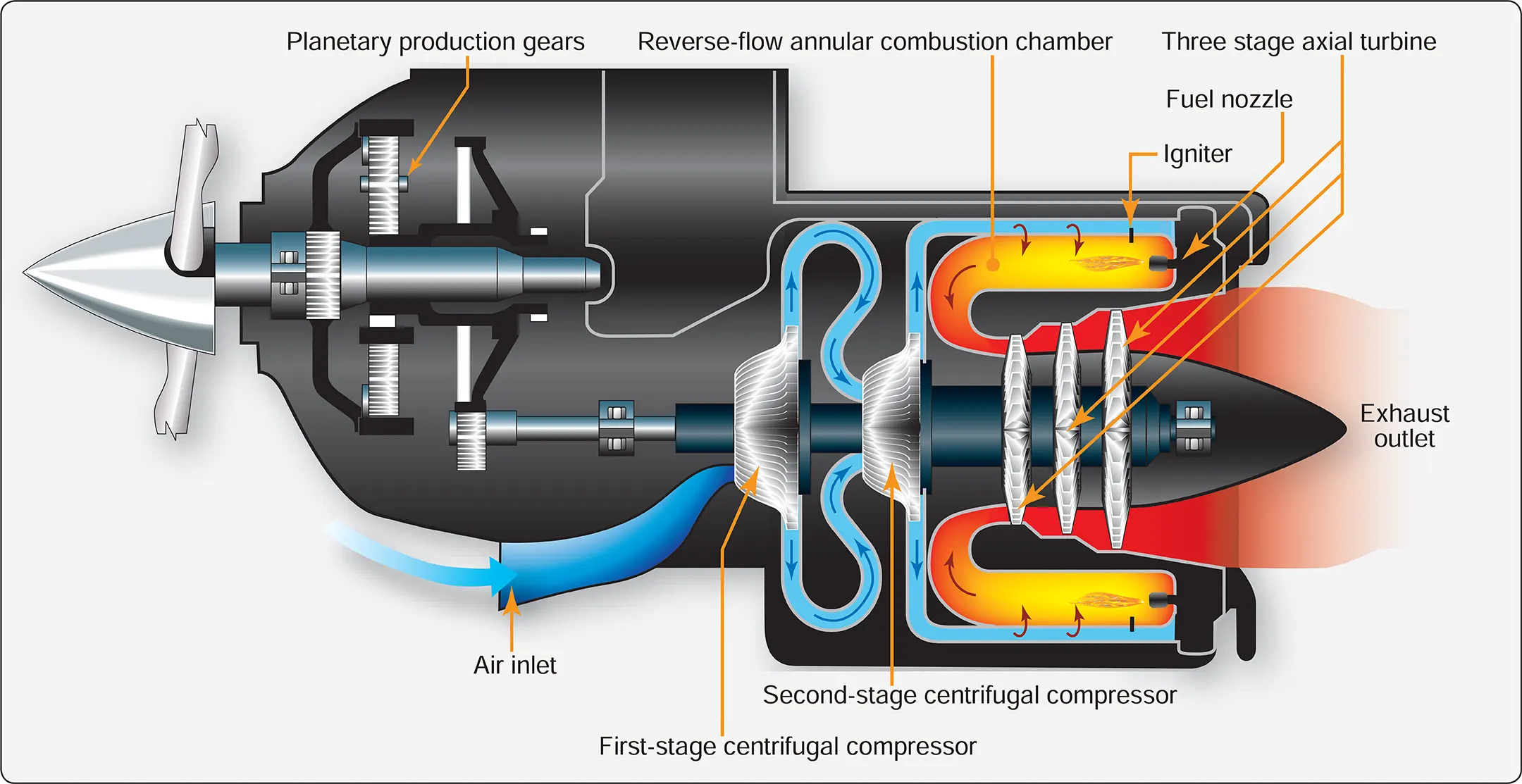
The gas mixture is initially ignited by high-energy igniter plugs, and the expanding combustion gases flow to the turbine. The energy of the hot, high-velocity gases is converted to torque on the main shaft by the turbine rotors. The reduction gear converts the high rpm—low torque of the main shaft to low rpm—high torque to drive the accessories and the propeller. The spent gases leaving the turbine are directed to the atmosphere by the exhaust pipe.
Most of the air passing through the engine provides internal cooling. Only about 10 percent of the air that passes through the engine is actually used in the combustion process. Up to approximately 20 percent of the compressed air may be bled off for the purpose of heating, cooling, cabin pressurization, and pneumatic systems. Over half the engine power is devoted to driving the compressor, and it is the compressor that can potentially produce very high drag in the case of a failed, windmilling engine.
In the fixed-shaft constant-speed engine, the engine rpm may be varied within a narrow range of 96 percent to 100 percent. During ground operation, the rpm may be reduced to 70 percent. In flight, the engine operates at a constant speed that is maintained by the governing section of the propeller. Power changes are made by increasing fuel flow and propeller blade angle rather than engine speed. An increase in fuel flow causes an increase in temperature and a corresponding increase in energy available to the turbine.
The turbine absorbs more energy and transmits it to the propeller in the form of torque. The increased torque forces the propeller blade angle to be increased to maintain the constant speed. Turbine temperature is a very important factor to be considered in power production. It is directly related to fuel flow and thus to the power produced. It needs to be limited because of strength and durability of the material in the combustion and turbine section. The control system schedules fuel flow to produce specific temperatures and to limit those temperatures so that the temperature tolerances of the combustion and turbine sections are not exceeded. The engine is designed to operate for its entire life at 100 percent. All of its components, such as compressors and turbines, are most efficient when operated at or near the rpm design point.
Powerplant (engine and propeller) control is achieved by means of a power lever and a condition lever for each engine. [Figure 3] There is no mixture control and/or rpm lever as found on piston-engine airplanes.
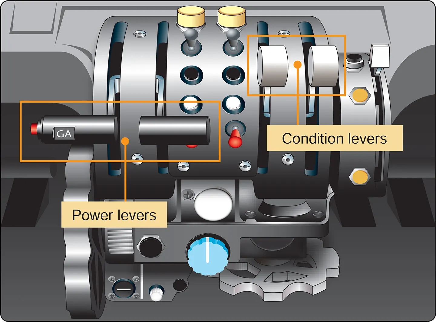
On the fixed-shaft constant-speed turboprop engine, the power lever is advanced or retarded to increase or decrease forward thrust. The power lever is also used to provide reverse thrust. The condition lever sets the desired engine rpm within a narrow range between that appropriate for ground operations and flight.
Powerplant instrumentation in a fixed-shaft turboprop engine typically consists of the following basic indicators. [Figure 4]
- Torque or horsepower
- Interturbine temperature (ITT)
- Fuel flow
- RPM
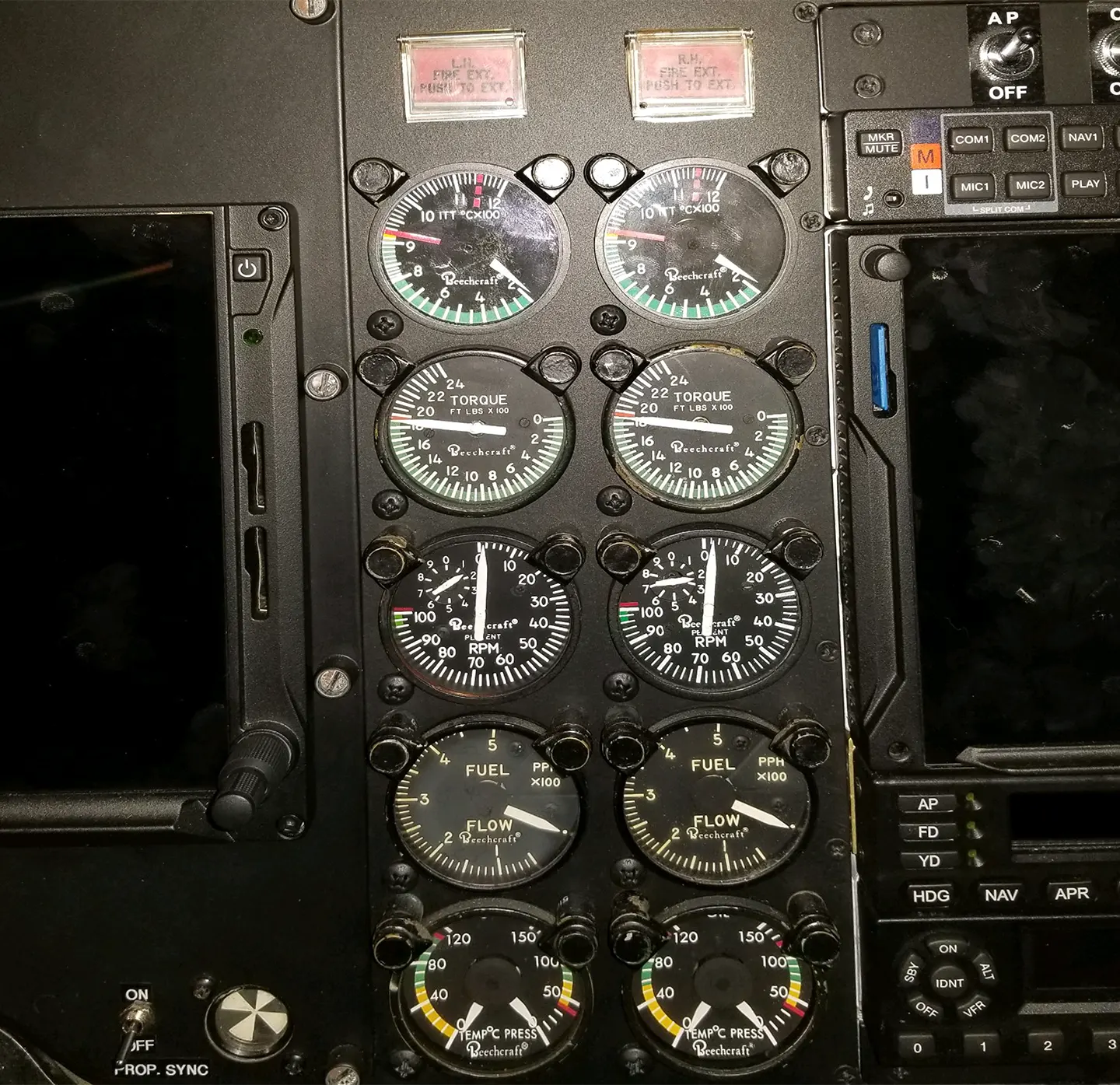
Torque developed by the turbine section is measured by a torque sensor. The torque is then reflected on the instrument panel horsepower gauge calibrated in horsepower times 100. ITT is a measurement of the combustion gas temperature between the first and second stages of the turbine section. The gauge is calibrated in degrees Celsius (°C). Propeller rpm is reflected on a tachometer as a percentage of maximum rpm. Normally, a vernier indicator on the gauge dial indicates rpm in 1 percent graduations as well. The fuel flow indicator indicates fuel flow rate in pounds per hour.
Propeller feathering in a fixed-shaft constant-speed turboprop engine is normally accomplished with the condition lever. An engine failure in this type engine, however, results in a serious drag condition due to the large power requirements of the compressor being absorbed by the propeller. This could create a serious airplane control problem in twin-engine airplanes unless the failure is recognized immediately and the affected propeller feathered. For this reason, the fixed-shaft turboprop engine is equipped with negative torque sensing (NTS).
NTS is a condition wherein propeller torque drives the engine, and the propeller is automatically driven to high pitch to reduce drag. The function of the negative torque sensing system is to limit the torque the engine can extract from the propeller during windmilling and thereby prevent large drag forces on the airplane. The NTS system causes a movement of the propeller blades automatically toward their feathered position should the engine suddenly lose power while in flight. The NTS system is an emergency backup system in the event of sudden engine failure. It is not a substitution for the feathering device controlled by the condition lever.
Split-Shaft/Free Turbine Engine
In a free power-turbine engine, such as the Pratt & Whitney PT-6 engine, the propeller is driven by a separate turbine through reduction gearing. The propeller is not on the same shaft as the basic engine turbine and compressor. [Figure 5] Unlike the fixed-shaft engine, in the split-shaft engine the propeller can be feathered in flight or on the ground with the basic engine still running. The free power-turbine design allows the pilot to select a desired propeller governing rpm, regardless of basic engine rpm.
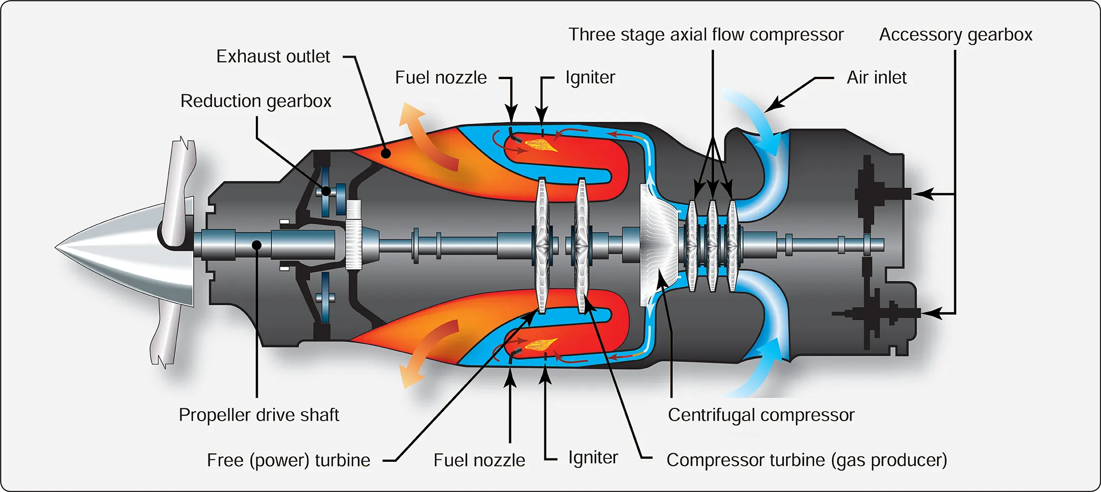
A typical free power-turbine engine has two independent counter-rotating turbines. One turbine drives the compressor, while the other drives the propeller through a reduction gearbox. The compressor in the basic engine consists of three axial flow compressor stages combined with a single centrifugal compressor stage. The axial and centrifugal stages are assembled on the same shaft and operate as a single unit.
Inlet air enters the engine via a circular plenum near the rear of the engine and flows forward through the successive compressor stages. The flow is directed outward by the centrifugal compressor stage through radial diffusers before entering the combustion chamber, where the flow direction is actually reversed. The gases produced by combustion are once again reversed to expand forward through each turbine stage. After leaving the turbines, the gases are collected in a peripheral exhaust scroll and are discharged to the atmosphere through two exhaust ports near the front of the engine.
A pneumatic fuel control system schedules fuel flow to maintain the power set by the gas generator power lever. Except in the beta range, propeller speed within the governing range remains constant at any selected propeller control lever position through the action of a propeller governor.
The accessory drive at the aft end of the engine provides power to drive fuel pumps, fuel control, oil pumps, a starter/generator, and a tachometer transmitter. At this point, the speed of the drive (N1) is the true speed of the compressor side of the engine, approximately 37,500 rpm.
Powerplant (engine and propeller) operation is achieved by three sets of controls for each engine: the power lever, propeller lever, and condition lever. [Figure 6]
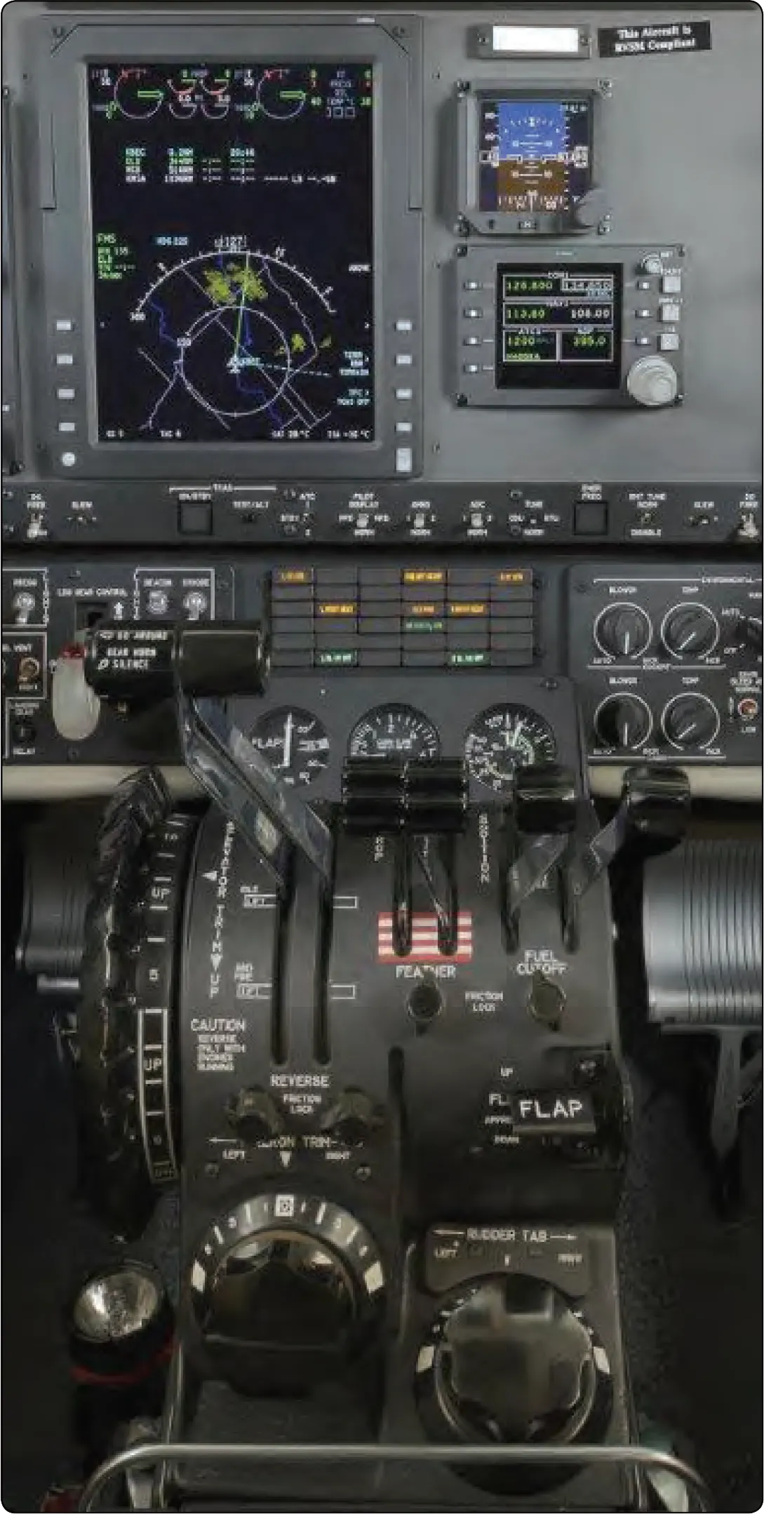
The power lever serves to control engine power in the range from idle through takeoff power. Forward or aft motion of the power lever increases or decreases gas generator rpm (N1) and thereby increases or decreases engine power. The propeller lever is operated conventionally and controls the constant-speed propellers through the primary governor. The propeller rpm range is normally from 1,500 to 1,900. The condition lever controls the flow of fuel to the engine. Like the mixture lever in a piston-powered airplane, the condition lever is located at the far right of the power quadrant. But the condition lever on a turboprop engine is really just an on/off valve for delivering fuel. There are HIGH IDLE and LOW IDLE positions for ground operations, but condition levers have no metering function. Leaning is not required in turbine engines; this function is performed automatically by a dedicated fuel control unit.
Engine instruments in a split-shaft/free turbine engine typically consist of the following basic indicators. [Figure 7]
- ITT indicator
- Torquemeter
- Propeller tachometer
- N1 (gas generator) tachometer
- Fuel flow indicator
- Oil temperature/pressure indicator
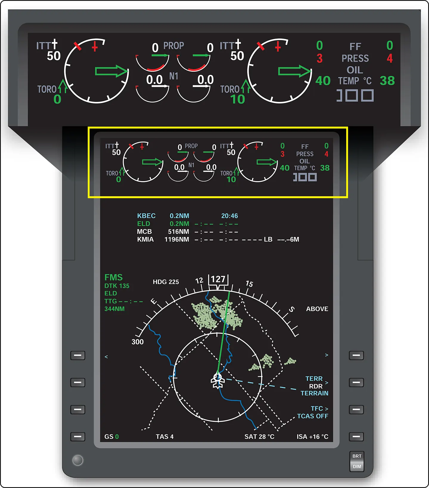
The ITT indicator gives an instantaneous reading of engine gas temperature between the compressor turbine and the power turbines. The torquemeter responds to power lever movement and gives an indication in foot-pounds (ft/lb) of the torque being applied to the propeller. Because in the free turbine engine the propeller is not attached physically to the shaft of the gas turbine engine, two tachometers are justified—one for the propeller and one for the gas generator. The propeller tachometer is read directly in revolutions per minute. The N1 or gas generator is read in percent of rpm. In the Pratt & Whitney PT-6 engine, it is based on a figure of 37,000 rpm at 100 percent. Maximum continuous gas generator is limited to 38,100 rpm or 101.5 percent N1.
The ITT indicator and torquemeter are used to set takeoff power. Climb and cruise power are established with the torquemeter and propeller tachometer while observing ITT limits. Gas generator (N1) operation is monitored by the gas generator tachometer. Proper observation and interpretation of these instruments provide an indication of engine performance and condition.
Reverse Thrust and Beta Range Operations
The thrust that a propeller provides is a function of the angle of attack (AOA) at which the air strikes the blades, and the speed at which this occurs. The AOA varies with the pitch angle of the propeller.
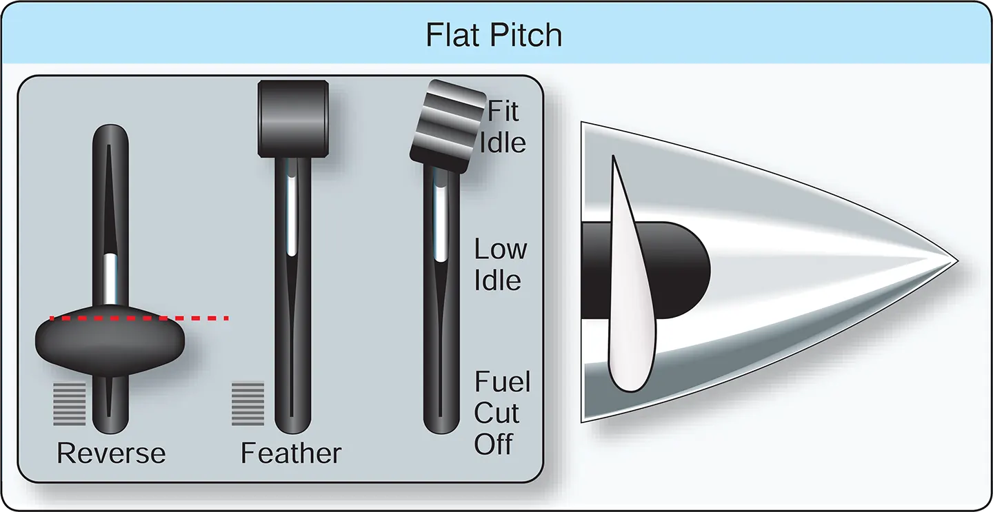
Forward pitch produces forward thrust—higher pitch angles being required at higher airplane speeds. [Figure 8A] So called “flat pitch,” shown in Figure 8B, is the blade position offering minimum resistance to rotation and no net thrust for moving the airplane.
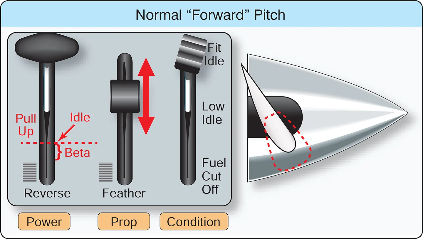
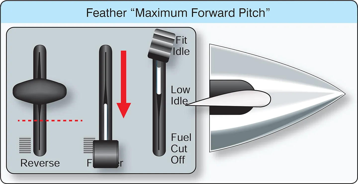
The “feathered” position is the highest pitch angle obtainable. [Figure 8C] The feathered position produces no forward thrust. The propeller is generally placed in feather only in case of in-flight engine failure to minimize drag and prevent the air from using the propeller as a turbine.
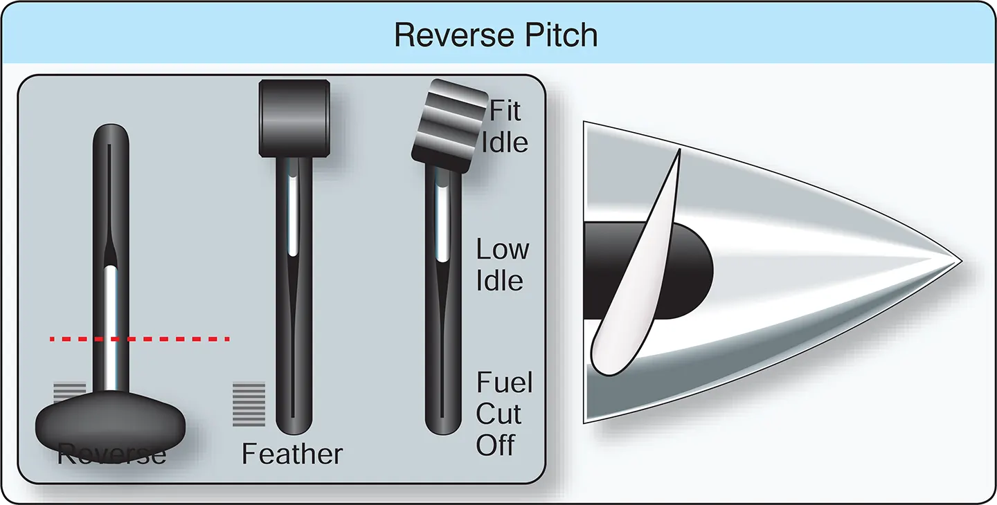
In the “reverse” pitch position, the engine/propeller turns in the same direction as in the normal (forward) pitch position, but the propeller blade angle is positioned to the other side of flat pitch. [Figure 8D] In reverse pitch, air is pushed away from the airplane rather than being drawn over it. Reverse pitch results in braking action, rather than forward thrust of the airplane. It is used for backing away from obstacles when taxiing, controlling taxi speed, or to aid in bringing the airplane to a stop during the landing roll. Reverse pitch does not mean reverse rotation of the engine. The engine delivers power just the same, no matter which side of flat pitch the propeller blades are positioned.
With a turboprop engine, in order to obtain enough power for flight, the power lever is placed somewhere between flight idle (in some engines referred to as “high idle”) and maximum. The power lever directs signals to a fuel control unit to manually select fuel. The propeller governor selects the propeller pitch needed to keep the propeller/engine on speed. This is referred to as the propeller governing or “alpha” mode of operation. When positioned aft of flight idle, however, the power lever directly controls propeller blade angle. This is known as the “beta” range of operation.
The beta range of operation consists of power lever positions from flight idle to maximum reverse. Beginning at power lever positions just aft of flight idle, propeller blade pitch angles become progressively flatter with aft movement of the power lever until they go beyond maximum flat pitch and into negative pitch, resulting in reverse thrust. While in a fixed-shaft/constant-speed engine, the engine speed remains largely unchanged as the propeller blade angles achieve their negative values. On the split-shaft PT-6 engine, as the negative 5° position is reached, further aft movement of the power lever also results in a progressive increase in engine (N1) rpm until a maximum value of about negative 11° of blade angle and 85 percent N1 are achieved.
Operating in the beta range and/or with reverse thrust requires specific techniques and procedures depending on the particular airplane make and model. Specific engine parameters and limitations for operations within this area should be adhered to. It is essential that a pilot transitioning to turboprop airplanes becomes knowledgeable and proficient in these areas, which are unique to turbine-engine powered airplanes.
Turboprop Airplane Electrical Systems
The typical turboprop airplane electrical system is a 28-volt direct current (DC) system, which receives power from one or more batteries and a starter/generator for each engine. The batteries are either lead-acid, nickel-cadmium (NiCad), or Lithium-ion. When battery voltage is low, its ability to turn the compressor for engine start is greatly diminished, and the possibility of engine damage due to a hot start increases. Therefore, it is essential to check the battery’s condition before every engine start. The different battery types have different operating characteristics depending on the specific aircraft installation and operational environment.
The DC generators used in turboprop airplanes double as starter motors and are called “starter/generators.” The starter/generator uses electrical power to produce mechanical torque to start the engine and then uses the engine’s mechanical torque to produce electrical power after the engine is running. Some of the DC power produced is changed to 28 volt 400 cycle alternating current (AC) power for certain avionic, lighting, and indicator synchronization functions. This is accomplished by an electrical component called an inverter.
The distribution of DC and AC power throughout the system is accomplished through the use of power distribution buses. These “buses” as they are called are actually common terminals from which individual electrical circuits get their power. [Figure 9]
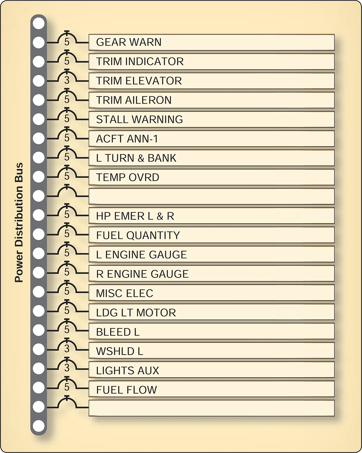
Buses are usually named for what they power (avionics bus, for example) or for where they get their power (right generator bus, battery bus). The distribution of DC and AC power is often divided into functional groups (buses) that give priority to certain equipment during normal and emergency operations. Main buses serve most of the airplane’s electrical equipment. Essential buses feed power to equipment having top priority. [Figure 10]
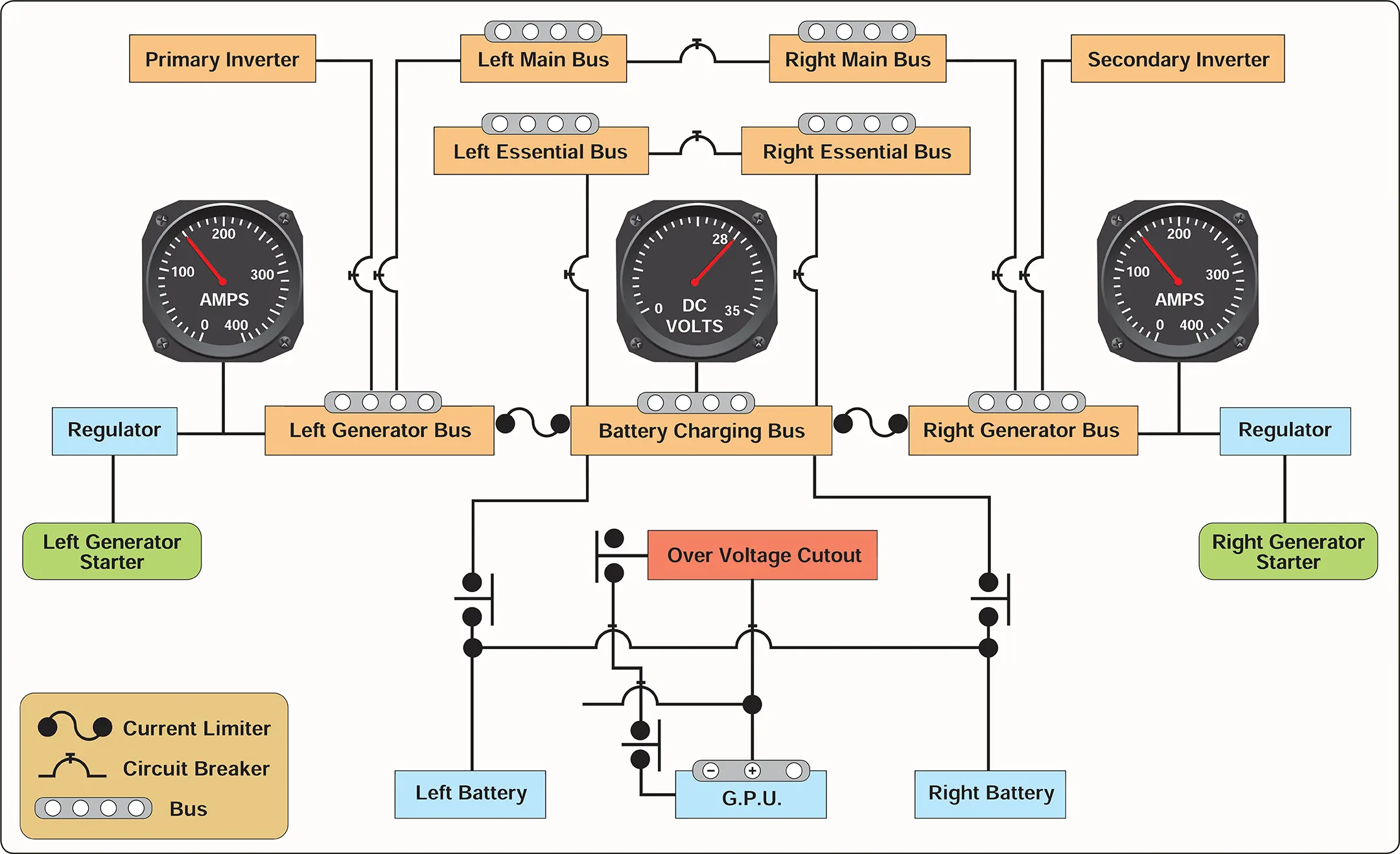
Multiengine turboprop airplanes normally have several power sources—at least one generator per engine and at least one battery for the airplane. The electrical systems are usually designed so that any bus can be energized by any of the power sources. For example, a typical system has a left and right engine generator-powered bus. While these buses are normally isolated, they may be fed from other power sources. However, in the event of a short-circuit, the bus remains isolated. Pilots should refer to the appropriate checklist when an electrical fault occurs.
Power distribution buses are protected from short circuits and other malfunctions by a type of fuse called a current limiter. In the case of excessive current supplied by any power source, the current limiter opens the circuit and thereby isolates that power source and separates the affected bus from the system. If this occurs, pilots should refer to the appropriate checklist.
Operational Considerations
As previously stated, a turboprop airplane flies just like any other piston engine airplane of comparable size and weight. It is the operation of the engines and airplane systems that makes the turboprop airplane different from its piston engine counterpart. Pilot errors in engine and/or systems operation are common causes of aircraft damage or loss of aircraft control. There are two engine-related issues that should be considered when a pilot transitions to turboprop operations.
The first issue concerns the split-shaft/free turbine engine, where power output lags for several seconds when the pilot moves the power lever from flight idle to a high power setting. This delay may surprise a pilot who has only flown airplanes with a piston engine (or a fixed-shaft turboprop). Certain operations such as firefighting and agricultural application require maneuvering close to the ground while operating at or near flight idle. Although smooth power applications are still the rule, the pilot should be aware that a greater physical movement of the power levers is required as compared to throttle movement in a piston engine. The pilot should understand the lag and anticipate and lead the power changes more than in the past and should keep in mind that the last 30 percent of engine rpm represents the majority of the engine thrust. Below that setting, the application of power has very little effect.
A second consideration for transitioning pilots concerns turbine engine heat sensitivity. A turbine engine cannot tolerate an over temperature condition for more than a very seconds without experiencing serious damage. Engine temperatures get hotter during starting than at any other time. Thus, turbine engines have minimum rotational speeds for introducing fuel into the combustion chambers during startup. Vigilant monitoring of temperature and acceleration on the part of the pilot remain crucial until the engine is running at a stable speed. Successful engine starting depends on assuring the correct minimum battery voltage before initiating start or employing a ground power unit (GPU) of adequate output.
After fuel is introduced to the combustion chamber during the start sequence, “light-off” and its associated heat rise occur very quickly. Engine temperatures may approach the maximum in a matter of 2 or 3 seconds before the engine stabilizes and temperatures fall into the normal operating range. During this time, the pilot should watch for any tendency of the temperatures to exceed limitations and be prepared to cut off fuel to the engine.
An engine tendency to exceed maximum starting temperature limits is termed a hot start. The temperature rise may be preceded by unusually high initial fuel flow, which may be the first indication the pilot has that the engine start is not proceeding normally. Serious engine damage occurs if the hot start is allowed to continue.
A condition where the engine is accelerating more slowly than normal is termed a hung start or false start. During a hung start/false start, the engine may stabilize at an engine rpm that is not high enough for the engine to continue to run without help from the starter. This is usually the result of low battery power or the starter not turning the engine fast enough for it to start properly.
Takeoffs in turboprop airplanes are not made by automatically pushing the power lever full forward to the stops. As stated earlier, depending on conditions, takeoff power may be limited by either torque or by engine temperature. Normally, the power lever position on takeoff is somewhat aft of full forward.
Takeoff and departure in a turboprop airplane (especially a twin-engine cabin-class airplane) should be accomplished in accordance with a standard takeoff and departure “profile” developed for the particular make and model. [Figure 11] The takeoff and departure profile should be in accordance with the airplane manufacturer’s recommended procedures as outlined in the Federal Aviation Administration (FAA)-approved Airplane Flight Manual and/or the Pilot’s Operating Handbook (AFM/POH). The increased complexity of turboprop airplanes makes the standardization of procedures a necessity for safe and efficient operation. The transitioning pilot should review the profile procedures before each takeoff to form a mental picture of the takeoff and departure process.
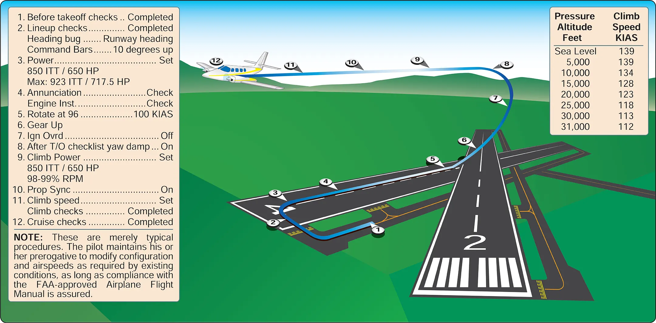
For any given high-horsepower operation, the pilot can expect that the engine temperature will climb as altitude increases at a constant power. On a warm or hot day, maximum temperature limits may be reached at a rather low altitude, making it impossible to maintain high horsepower to higher altitudes. Also, the engine’s compressor section has to work harder with decreased air density. Power capability is reduced by high-density altitude and power use may have to be modulated to keep engine temperature within limits.
In a turboprop airplane, the pilot can close the throttles(s) at any time without concern for cooling the engine too rapidly. Consequently, rapid descents with the propellers in low pitch can be dramatically steep. Like takeoffs and departures, approach and landing should be accomplished in accordance with a standard approach and landing profile. [Figure 12] However, when flying an airplane equipped with a split shaft/free turbine engine, the pilot should anticipate the demand for power and account for any lag in “spool-up” time.
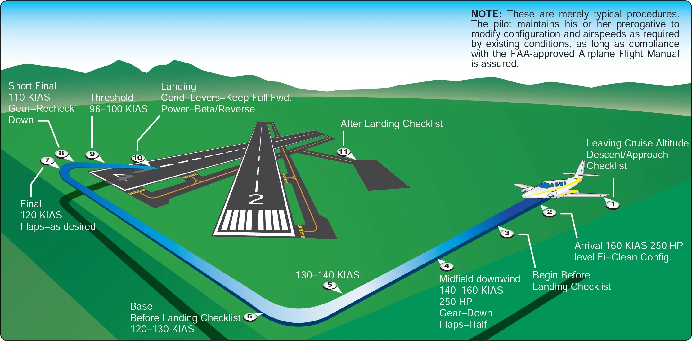
A stabilized approach is an essential part of the approach and landing process. In a stabilized approach, the airplane, depending on design and type, is placed in a stabilized descent on a glidepath ranging from 2.5 to 3.5°. The speed is stabilized at some reference from the AFM/POH—usually 1.25 to 1.30 times the stall speed in approach configuration. The descent rate is stabilized from 500 fpm to 700 fpm until the landing flare.
Landing some turboprop airplanes (as well as some piston twins) can result in a hard, premature touchdown if the engines are idled too soon. This is because large propellers spinning rapidly in low pitch create considerable drag. In such airplanes, it may be preferable to maintain power throughout the landing flare and touchdown. Once firmly on the ground, propeller beta range operation dramatically reduces the need for braking in comparison to piston airplanes of similar weight.
Training Considerations
The medium and high altitudes at which turboprop airplanes are flown provide an entirely different environment in terms of regulatory requirements, airspace structure, physiological requirements, and even meteorology. The pilot transitioning to turboprop airplanes, particularly those who are not familiar with operations in the high/medium altitude environment, should approach turboprop transition training with this in mind. Thorough ground training should cover all aspects of high/medium altitude flight, including the flight environment, weather, flight planning and navigation, physiological aspects of high-altitude flight, oxygen and pressurization system operation, and high-altitude emergencies.
Flight training should prepare the pilot to demonstrate a comprehensive knowledge of airplane performance, systems, emergency procedures, and operating limitations, along with a high degree of proficiency in performing all flight maneuvers and in-flight emergency procedures. The training outline below covers information used by pilots to operate safely at high altitudes.
Ground Training
1. High-Altitude Flight Environment
- Airspace and Reduced Vertical Separation Minimum (RVSM) Operations
- Title 14 Code of Federal Regulations (14 CFR) part 91, section 91.211, Requirements for Use of Supplemental Oxygen
2. Weather
- Atmosphere
- Winds and clear air turbulence
- Icing
3. Flight Planning and Navigation
- Flight planning
- Weather charts
- Navigation
- Navigation aids (NAVAIDs)
- High Altitude Redesign (HAR)
- RNAV/Required Navigation Performance (RNP) and Receiver Autonomous Integrity Monitoring (RAIM) prediction
4. Physiological Training
- Respiration
- Hypoxia
- Effects of prolonged oxygen use
- Decompression sickness
- Vision
- Altitude chamber (optional)
5. High-Altitude Systems and Components
- Oxygen and oxygen equipment
- Pressurization systems
- High-altitude components
6. Aerodynamics and Performance Factors
- Acceleration and deceleration
- Gravity (G)-forces
- Mach Tuck and Mach Critical (turbojet airplanes)
- Swept-wing concept
7. Emergencies
- Decompression
- Donning of oxygen masks
- Failure of oxygen mask or complete loss of oxygen supply/system
- In-flight fire
- Flight into severe turbulence or thunderstorms
- Compressor stalls
Flight Training
1. Preflight Briefing
2. Preflight Planning
- Weather briefing and considerations
- Course plotting
- Airplane Flight Manual (AFM)
- Flight plan
3. Preflight Inspection
- Functional test of oxygen system, including the verification of supply and pressure, regulator operation, oxygen flow, mask fit, and pilot and air traffic control (ATC) communication using mask microphones
4. Engine Start Procedures, Run-up, Takeoff, and Initial Climb
5. Climb to High Altitude and Normal Cruise Operations While Operating Above 25,000 Feet Mean Sea Level (MSL)
6. Emergencies
- Simulated rapid decompression, including the immediate donning of oxygen masks
- Emergency descent
7. Planned Descents
8. Shutdown Procedures
9. Postflight Discussion
