Electrical System
The loss of electrical power can deprive the pilot of numerous critical systems, and therefore should not be taken lightly even in day/visual flight rules (VFR) conditions. Most in-flight failures of the electrical system are located in the generator or alternator. Once the generator or alternator system goes off line, the electrical source in a typical light airplane is a battery. If a warning light or ammeter indicates the probability of an alternator or generator failure in an airplane with only one generating system, however, the pilot may have very little time available from the battery.
The rating of the airplane battery provides a clue as to how long it may last. With batteries, the higher the amperage load, the faster any available stored energy gets consumed. Thus, a 25-amp hour battery could produce 5 amps per hour for 5 hours, but if the load were increased to 10 amps, it might last only 2 hours. A 40-amp load might discharge the battery fully in about 10 or 15 minutes. Much depends on the battery condition at the time of the system failure.
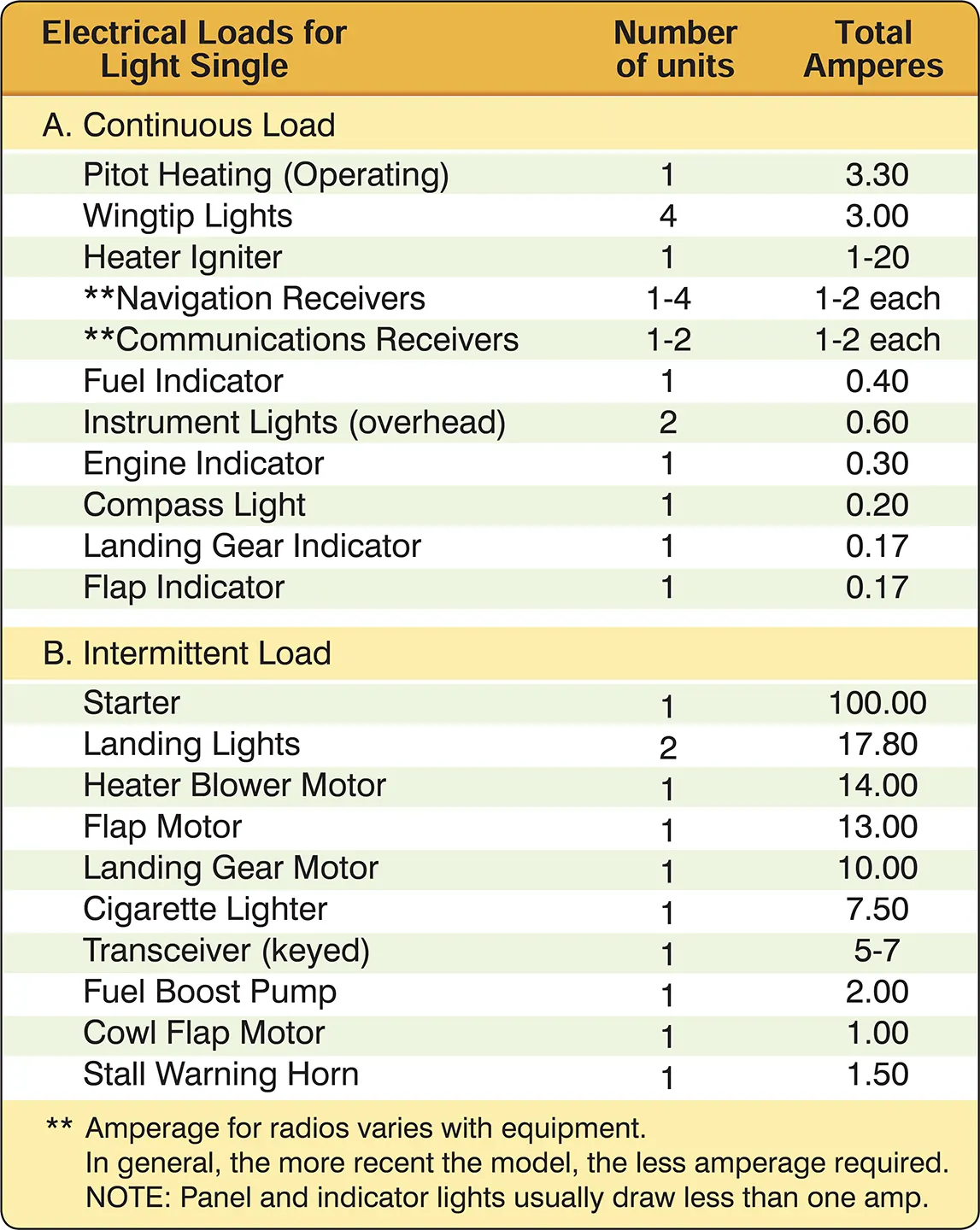
If the battery has been in service for a few years, its power may be reduced substantially because of internal resistance. Or if the system failure was not detected immediately, much of the stored energy may have already been used. It is essential, therefore, that the pilot immediately shed non-essential loads when the generating source fails. [Figure 1] The pilot should then plan to land at the nearest suitable airport.

What constitutes an “emergency” load following a generating system failure cannot be predetermined because the actual circumstances are always somewhat different—for example, whether the flight is VFR or instrument flight rules (IFR), conducted in day or at night, in clouds or in the clear. Distance to nearest suitable airport can also be a factor.
The pilot should remember that the electrically-powered (or electrically-selected) landing gear and flaps do not function properly on the power left in a partially-depleted battery. Landing gear and flap motors use power at rates much greater than most other types of electrical equipment. The result of selecting these motors on a partially-depleted battery may well result in an immediate total loss of electrical power.
If the pilot expects an imminent and complete in-flight loss of electrical power, the following steps should be taken:
- Shed all but the most necessary electrically-driven equipment.
- Understand that any loss of electrical power is critical in a small airplane—notify ATC of the situation immediately. Request radar vectors for a landing at the nearest suitable airport.
- If landing gear or flaps are electrically controlled or operated, plan the arrival well ahead of time. Expect to make a no-flap landing and anticipate a manual landing gear extension.
Pitot-Static System
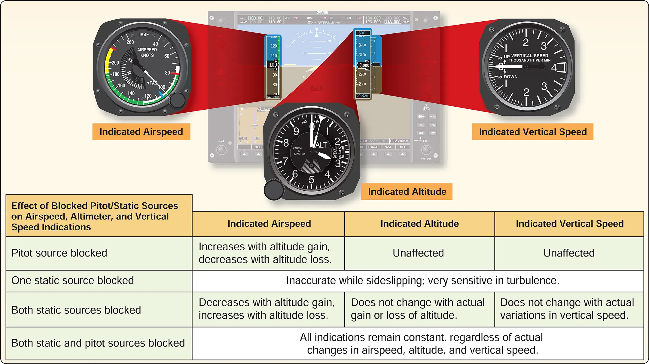
The source of the pressure for operating the airspeed indicator, the vertical speed indicator (VSI), and the altimeter is the pitot-static system. The major components of the pitot-static system are the impact pressure chamber and lines and the static pressure chamber and lines, each of which are subject to total or partial blockage by ice, dirt, and/or other foreign matter. Blockage of the pitot-static system adversely affects instrument operation. [Figure 2]

Partial static system blockage is insidious in that it may go unrecognized until a critical phase of flight. During takeoff, climb, and level-off at cruise altitude the altimeter, airspeed indicator, and VSI may operate normally. No indication of malfunction may be present until the airplane begins a descent.
If the static reference system is severely restricted, but not entirely blocked, as the airplane descends, the static reference pressure at the instruments begins to lag behind the actual outside air pressure. While descending, the altimeter may indicate that the airplane is higher than actual because the obstruction slows the airflow from the static port to the altimeter. The VSI confirms the altimeter’s information regarding rate of change because the reference pressure is not changing at the same rate as the outside air pressure. The airspeed indicator, unable to tell whether it is experiencing more airspeed pitot pressure or less static reference pressure, indicates a higher airspeed than actual. To the pilot, the instruments indicate that the airplane is too high, too fast, and descending at a rate much lower than desired.
If the pilot levels off and then begins a climb, the altitude indication may still lag. The VSI indicates that the airplane is not climbing as fast as actual. The indicated airspeed, however, may begin to decrease at an alarming rate. The least amount of pitch-up attitude may cause the airspeed needle to indicate dangerously near stall speed.
Managing a static system malfunction requires that the pilot know and understand the airplane’s pitot-static system. If a system malfunction is suspected, the pilot should confirm it by opening the alternate static source. This should be done while the airplane is climbing or descending. If the instrument needles move significantly when this is done, a static pressure problem exists and the alternate source should be used during the remainder of the flight.
Failure of the pitot-static system may also have serious consequences for Electronic Flight Instrument Systems (EFIS). To satisfy the requirements of Title 14 of the Code of Federal Regulations (14 CFR) part 23, section 23.2615(b)(2), information essential for continued safe flight and landing will be available to the flightcrew in a timely manner after any single failure or probable combination of failures. However, many of the light aircraft equipped with glass displays typically share the same pitot-static inputs for the backup instrumentation. Since both systems are receiving the same input signals, both could fail if affected by obstructed or blocked pitot tubes and static ports and create a difficult situation for a pilot flying in IMC. Some manufacturers combine both the air data computer (ADC) and the attitude and heading reference system (AHRS) functions so that a blockage of the input system may also affect the attitude display.
With conventional instrumentation, the design and operation are similar regardless of aircraft or manufacturer. By comparing information between the six conventional instruments, pilots are able to diagnose common failure modes. Instrument failure indications of conventional instruments and electronic flight displays may be entirely different, and electronic systems failure indications are not standardized. With the wide diversity in system design of glass displays, the primary display and the backup display may respond differently to any interruption of data input, and both displays may function differently than conventional instruments under the same conditions.
It is imperative for pilots to obtain equipment-specific information in reference to both the aircraft and the avionics that fully prepare them to interpret and properly respond to equipment malfunctions of electronic flight instrument displays. Rapidly changing equipment, complex systems, and the difficulty or inability to simulate failure modes and functions can impose training limitations. Pilots still should be able to respond to equipment malfunctions in a timely manner without impairing other critical flight tasks should the need arise.
