Center of Gravity (CG)
In addition to overloading or drastically reducing the aircraft’s weight, the distribution of weight is also a concern. When aircraft equipment is changed, the person making the equipment change must make an entry on the equipment list indicating items added, removed, or relocated; the date of the change; and the person’s name and certification number in the aircraft’s maintenance records.
For the purpose of weight and balance computations, the CG of an airplane is an imaginary point about which the nose-heavy (–) moments and tail-heavy (+) moments are exactly equal in magnitude. If suspended from the CG point, the aircraft would have no tendency to rotate nose up or nose down. The CG of the loaded aircraft can range fore and aft within certain limits that are determined during the flght test for type certifiction. These limits are the most forward- and rearward-loaded CG positions at which the aircraft meets the performance and flightcharacteristics required by the FAA.
Any loading that places the CG outside the limits for a particular aircraft seriously impairs the pilot’s ability to control the aircraft. For example, it is more difficultto take off and gain altitude in a nose-heavy aircraft, and the aircraft tends to drop its nose when the pilot reduces throttle. It also requires a higher speed to land safely. A tail-heavy aircraft is more susceptible to stalling at low speed, which is a concern during the landing approach.
On small airplanes and on all helicopters, the CG location is identified as being a specific number of inches from the datum. The CG range is identified in the same way. On larger airplanes, from private business jets to large jumbo jets, the CG and its range are typically identified in relation to the width of the wing.
Mean Aerodynamic Chord (MAC)
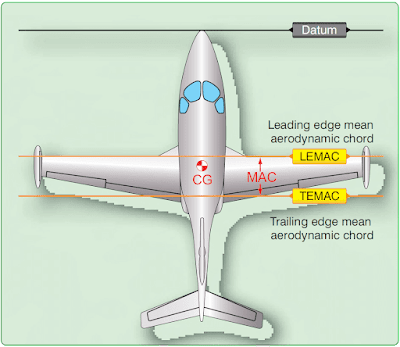
The width of the wing, or straight-line distance from the leading edge to the trailing edge, on an airplane is known as the chord. If the leading edge and the trailing edge of a wing are parallel, the chord is equal at all points along the entire length of the wing. The average length of the chord, or MAC, of a tapered wing is more complicated to define.The MAC, as seen in Figure 1, is the chord of an imaginary airfoil that has the same aerodynamic characteristics as the actual airfoil. You can also think of it as the chord drawn through the geographic center of the plan area of the wing.
 |
| Figure 1. The MAC is the chord drawn through the geographic center of the plan area of the wing |
Usually listed in the aircraft’s TCDS when it is required for weight and balance computations, the MAC is established by the manufacturer, defining its leading edge (LEMAC) and trailing edge (TEMAC) in terms of inches from the datum. [Figure 1] The CG location and various limits are then expressed in percentage of the chord or percent MAC. In order to relate the percent MAC to the datum, all weight and balance information includes two items: the MAC length in inches and the location of the LEMAC in inches from the datum. For the purpose of simplicity, most light-aircraft manufacturers express the CG range in inches from the datum; transport-category aircraft CGs are expressed in percent MAC.
The relative positions of the CG and the aerodynamic center of lift of the wing have critical effects on the flightcharacteristics of the aircraft. Consequently, relating the CG location to the chord of the wing is convenient from a design and operations standpoint. Normally, an aircraft has acceptable flght characteristics if the CG is located somewhere near the 25 percent average chord point. This means the CG is located one-fourth of the distance back from the LEMAC to the TEMAC. Such a location places the CG forward of the aerodynamic center for most airfoils.
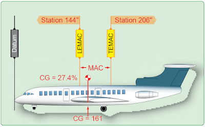
The weight and balance data of the airplane in Figure 2 states that the MAC is from stations 144 to 206 and the CG is located at station 161.
 |
| Figure 2. Large aircraft weight and balance calculation diagram |
MAC = TEMAC – LEMAC
MAC = 206″ – 144″
MAC = 62″
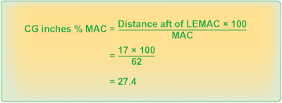
In order to find the percent MAC, firs determine the distance of the CG from LEMAC.
CG – LEMAC = Distance from LEMAC
161″ – 144″ = 17″
 |
| Figure 3. Formula for determining the CG expressed in percent MAC |
The CG of the airplane is located at 27.4 percent MAC.
MAC = 206 – 144 = 62
LEMAC = station 144
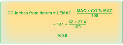
Determine the location of the CG in inches from the datum by using the formula found in Figure 4.
 |
| Figure 4. Formula for determining the CG in inches from the datum |
The CG of this airplane is located at station 160.9 inches aft of the datum. It is important for longitudinal stability that the CG be located ahead of the center of lift of a wing. Since the center of lift is expressed as percent MAC, the location of the CG is expressed in the same terms.
