
A pilot’s ability to predict the performance of a helicopter is extremely important. It helps to determine how much weight the helicopter can carry before takeoff, if the helicopter can safely hover at a specific altitude and temperature, the distance required to climb above obstacles, and what the maximum climb rate will be.
Factors Affecting Performance
Moisture (Humidity)
Weight
Weight is one of the most important factors because the pilot can control it. Most performance charts include weight as one of the variables. By reducing the weight of the helicopter, a pilot may be able to take off or land safely at a location that otherwise would be impossible. However, if ever in doubt about whether a takeoff or landing can be performed safely, delay your takeoff until more favorable density altitude conditions exist. If airborne, try to land at a location that has more favorable conditions, or one where a landing can be made that does not require a hover.
In addition, at higher gross weights, the increased power required to hover produces more torque, which means more antitorque thrust is required. In some helicopters during high altitude operations, the maximum antitorque produced by the tail rotor during a hover may not be sufficient to overcome torque even if the gross weight is within limits.
Winds
The wind direction is also an important consideration. Headwinds are the most desirable as they contribute to the greatest increase in performance. Strong crosswinds and tailwinds may require the use of more tail rotor thrust to maintain directional control. This increased tail rotor thrust absorbs power from the engine, which means there is less power available to the main rotor for the production of lift. Some helicopters even have a critical wind azimuth or maximum safe relative wind chart. Operating the helicopter beyond these limits could cause loss of tail rotor effectiveness.
Takeoff and climb performance is greatly affected by wind. When taking off into a headwind, effective translational lift is achieved earlier, resulting in more lift and a steeper climb angle. When taking off with a tailwind, more distance is required to accelerate through translation lift.
Performance Charts
Using these assumptions, the manufacturer develops performance data for the helicopter based on actual flight tests. However, they do not test the helicopter under each and every condition shown on a performance chart. Instead, they evaluate specific data and mathematically derive the remaining data.
Height/Velocity Diagram
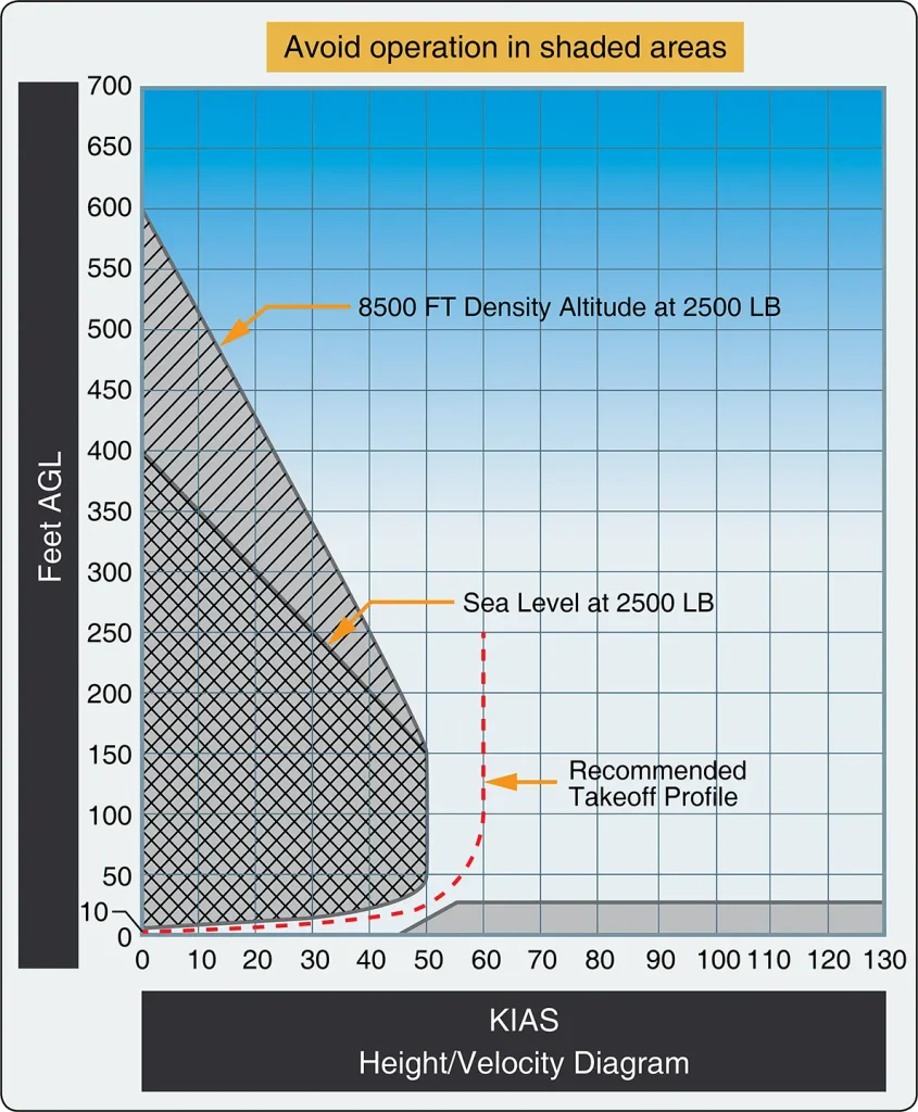
The grey portion on the left side of the diagram marks a flight profile that probably does not allow the pilot to complete an autorotation successfully, primarily due to having insufficient airspeed to enter an autorotative profile in time to avoid a crash. The shaded area on the lower right is dangerous due to the airspeed and proximity to the ground resulting in dramatically reduced reaction time for the pilot in the case of mechanical failure, or other in-flight emergencies. This shaded area at the lower right is not portrayed in H/V diagrams for multiengine helicopters capable of safely hovering and flying with a single engine failure.
The following examples further illustrate the relevance of the H/V diagram to a single-engine helicopter.
At low heights with low airspeed, such as a hover taxi, the pilot can simply use the kinetic energy from the rotor disk to cushion the landing with collective, converting rotational inertia to lift. The aircraft is in a safe part of the H/V diagram. At the extreme end of the scale (e.g., a three-foot hover taxi at walking pace) even a complete failure to recognize the power loss resulting in an uncushioned landing would probably be survivable.
As the airspeed increases without an increase in height, there comes a point at which the pilot’s reaction time would be insufficient to react with a flare in time to prevent a high speed, and thus probably fatal, ground impact. Another thing to consider is the length of the tailboom and the response time of the helicopter flight controls at slow airspeeds and low altitudes. Even small increases in height give the pilot much greater time to react; therefore, the bottom right part of the H/V diagram is usually a shallow gradient. If airspeed is above ideal autorotation speed, the pilot’s instinct is usually to flare to convert speed to height and increase rotor rpm through coning, which also immediately gets them out of the dead man’s curve.
Conversely, an increase in height without a corresponding increase in airspeed puts the aircraft above a survivable uncushioned impact height, and eventually above a height where rotor inertia can be converted to sufficient lift to enable a survivable landing. This occurs abruptly with airspeeds much below the ideal autorotative speed (typically 40–80 knots). The pilot must have enough time to accelerate to autorotation speed in order to autorotate successfully; this directly relates to a requirement for height. Above a certain height the pilot can achieve autorotation speed even from a zero knot start, thus putting high OGE hovers outside the curve.
The typical safe takeoff profile involves initiation of forward flight from a 2–3 feet landing gear height, only gaining altitude as the helicopter accelerates through translational lift, as airspeed approaches a safe autorotative speed. At this point, some of the increased thrust available may be used to attain safe climb airspeed, which will keep the helicopter out of the shaded or hatched areas of the H/V diagram. Although helicopters are not restricted from conducting maneuvers that will place them in the shaded area of the H/V diagram, it is important for pilots to understand that operation in those shaded areas exposes pilot, aircraft, and passengers to a certain hazard should the engine or driveline malfunction. The pilot should always evaluate the risk of the maneuver versus the operational value.
The Effect of Weight Versus Density Altitude
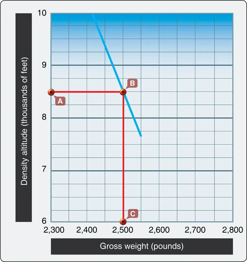
The production of performance charts and diagrams for helicopters are regulatory as set out in Title 14 of the Code of Federal Regulations (14 CFR) Part 27, Airworthiness Standards. These charts establish safer parameters for operation. Although not regulatory, the pilot should carry out a full risk assessment to carefully consider the higher risk before operating within the shaded areas of the height/ velocity diagram.
Autorotational Performance
During autorotation gravity provides the source of energy powering the rotor by causing upflow up through the rotor during descent. This is the same as saying that potential energy is being traded for kinetic energy to turn the rotor as the aircraft descends.
In Figure 3, the S-300 curve shows the various combinations of horizontal and vertical speeds that supply the required energy to keep the rotor turning at a constant 471 rpm. For example, an airspeed of 54 mph with a corresponding vertical speed of 1,600 feet per minute (fpm) will provide enough kinetic energy to maintain the rotor at a 471 rpm. The rotor does not care if the air is coming from the front or the bottom so long as the total is sufficient to maintain the rpm. Any point on the curve will maintain rotor speed. However, the pilot does care because if he or she, for example, glides at 30 knots, the corresponding rate of descent will be over 2,200 fpm. Since there is little airspeed for a deceleration (or “flare”) to reduce the rate of decent before touchdown, the collective pitch application (increasing blade pitch and giving a final temporary increase in lift before the blades slow down) may be insufficient to arrest the rate of descent.
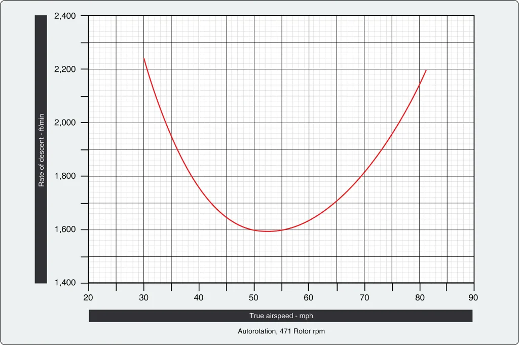
Referencing a curve similar to the one shown in Figure 3 is useful to understand the consequences of not maintaining the target airspeed when executing an autorotation. Simply put, the pilot should know why airspeed is the most significant factor affecting the rate of descent.
Hovering Performance
As density altitude increases, more power is required to hover. At some point, the power required is equal to the power available. This establishes the hovering ceiling under the existing conditions. Any adjustment to the gross weight by varying fuel, payload, or both, affects the hovering ceiling. The heavier the gross weight, the lower the hovering ceiling. As gross weight is decreased, the hover ceiling increases.
Sample Hover Problem 1
You are to fly a photographer to a remote location to take pictures of the local wildlife.
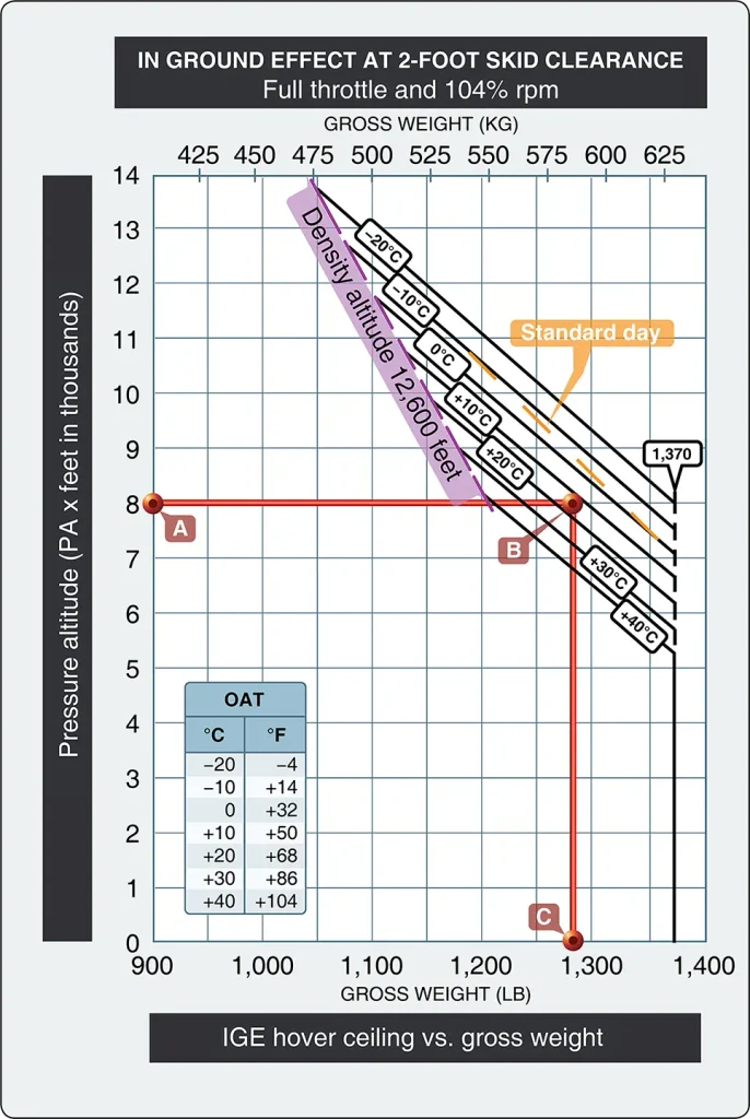
A. Pressure Altitude: 8,000 feet
B. Temperature: +15 °C
C. Takeoff Gross Weight:1,250 lb
rpm:104 percent
First enter the chart at 8,000 feet pressure altitude (point A), then move right until reaching a point midway between the +10 °C and +20 °C lines (point B). From that point, proceed down to find the maximum gross weight where a 2 foot hover can be achieved. In this case, it is approximately 1,280 pounds (point C).
Since the gross weight of your helicopter is less than this, you can safely hover with these conditions.
Sample Hover Problem 2
Once you reach the remote location in the previous problem, you will need to hover OGE for some of the pictures. The pressure altitude at the remote site is 9,000 feet, and you will use 50 pounds of fuel getting there. (The new gross weight is now 1,200 pounds.) The temperature will remain at +15 °C.
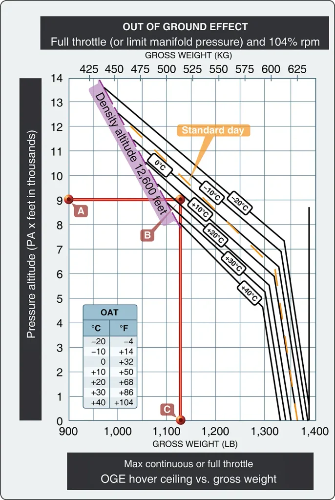
These two sample problems emphasize the importance of determining the gross weight and hover ceiling throughout the entire flight operation. Being able to hover at the takeoff location with a specific gross weight does not ensure the same performance at the landing point. If the destination point is at a higher density altitude because of higher elevation, temperature, and/or relative humidity, more power is required to hover there. You should be able to predict whether hovering power will be available at the destination by knowing the temperature and wind conditions, using the performance charts in the helicopter flight manual, and making certain power checks during hover and in flight prior to commencing the approach and landing.
For helicopters with dual engines, performance charts provide torque amounts for both engines.
Sample Hover Problem 3
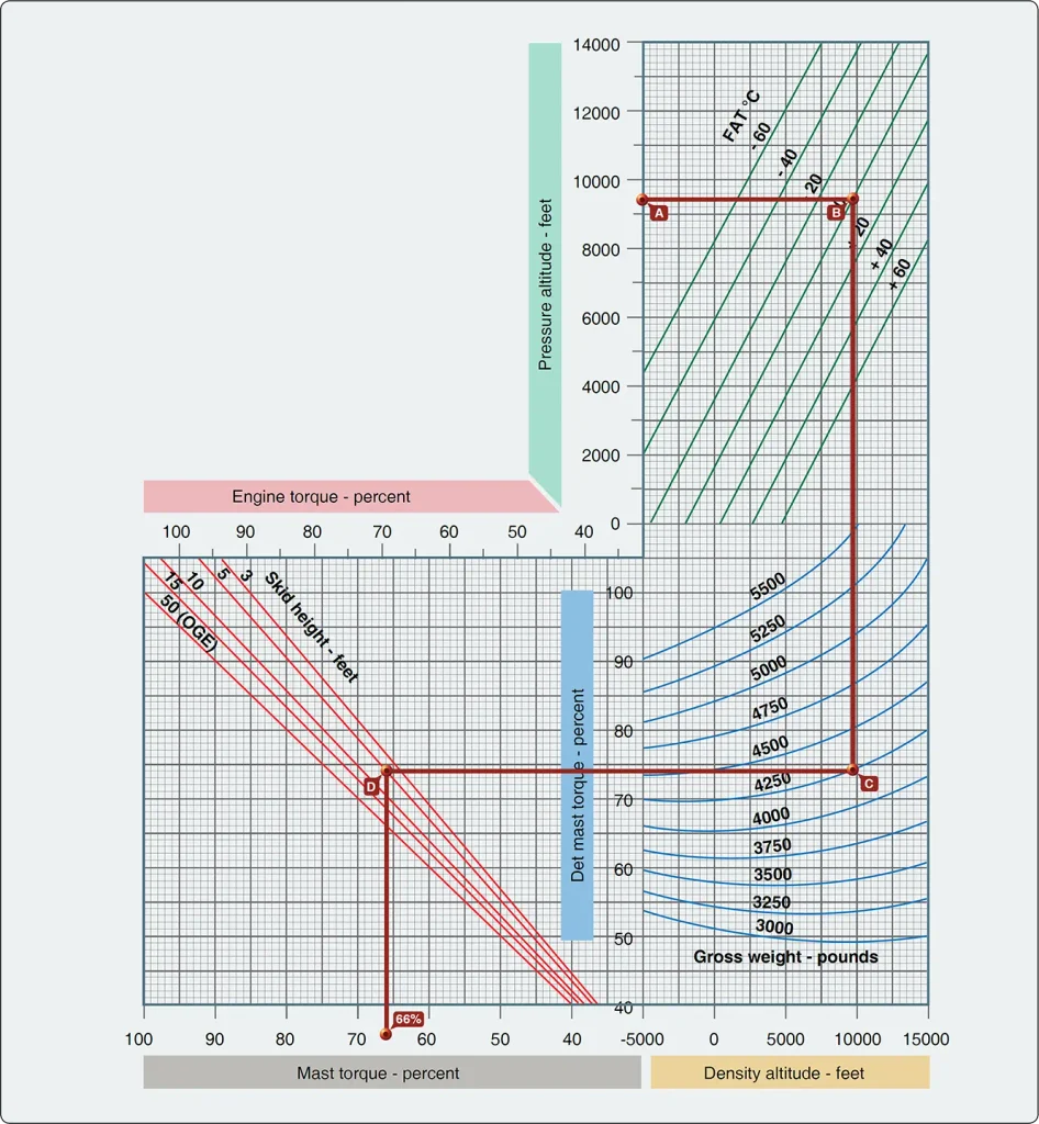
Use the following conditions:
A. Pressure Altitude: 9,500 feet
B. Outside Air Temperature.: 0 °C
C. Gross Weight: 4,250 lb
D. Desired Skid Height: 5 feet
First, enter the chart at 9,500 feet pressure altitude, then move right to outside air temperature, 0 °C. From that point, move down to 4,250 pounds gross weight and then move left to 5-foot skid height. Drop down to read 66 percent torque required to hover.
Climb Performance
A helicopter flown at the best rate-of-climb speed (VY) obtains the greatest gain in altitude over a given period of time. This speed is normally used during the climb after all obstacles have been cleared and is usually maintained until reaching cruise altitude. Rate of climb must not be confused with angle of climb. Angle of climb is a function of altitude gained over a given distance. The VY results in the highest climb rate, but not the steepest climb angle, and may not be sufficient to clear obstructions. The best angle of climb speed (VX) depends upon the power available. If there is a surplus of power available, the helicopter can climb vertically, so VX is zero.
Wind direction and speed have an effect on climb performance, but it is often misunderstood. Airspeed is the speed at which the helicopter is moving through the atmosphere and is unaffected by wind. Atmospheric wind affects only the groundspeed, or speed at which the helicopter is moving over the Earth’s surface. Thus, the only climb performance affected by atmospheric wind is the angle of climb and not the rate of climb.
When planning for climb performance, it is first important to plan for torque settings at level flight. Climb performance charts show the change in torque, above or below torque, required for level flight under the same gross weight and atmospheric conditions to obtain a given rate of climb or descent.
Sample Cruise or Level Flight Problem
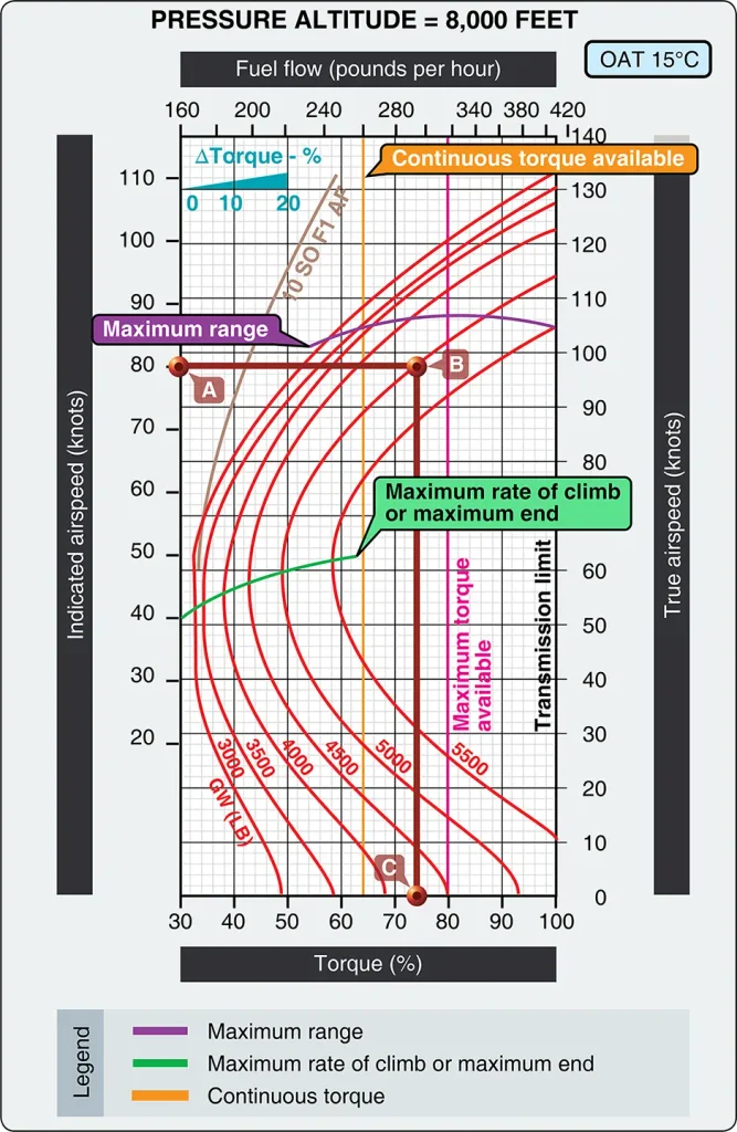
Pressure Altitude: 8,000 feet
Outside Air Temperature: +15 °C
A. Indicated Airspeed: 80 knots
B. Maximum Gross Weight: 5,000 lb
With this chart, first confirm that it is for a pressure altitude of 8,000 feet with an OAT of 15°. Begin on the left side at 80 knots indicated airspeed (point A) and move right to maximum gross weight of 5,000 lb (point B). From that point, proceed down to the torque reading for level flight, which is 74 percent torque (point C). This torque setting is used in the next problem to add or subtract cruise/descent torque percentage from cruise flight.
Sample Climb Problem
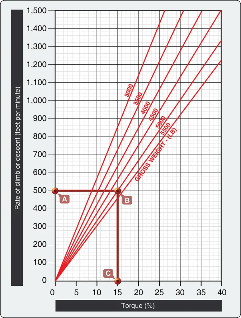
A. Rate of Climb or Descent: 500 fpm
B. Maximum Gross Weight: 5,000 lb
With this chart, first locate a 500-fpm rate of climb or descent (point A), and then move to the right to a maximum gross weight of 5,000 lb (point B). From that point, proceed down to the torque percentage, which is 15 percent torque (point C). For climb or descent, 15 percent torque should be added/subtracted from the 74 percent torque needed for level flight. For example, if the numbers were to be used for a climb torque, the pilot would adjust torque settings to 89 percent for optimal climb performance.